


RS-232C Interface
122
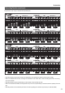
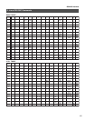
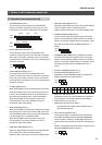
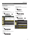
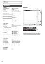
• MONITOR MODE SENSE (DBH) [JVC-1]
Returns the status data for the monitor display settings.
MONITOR MODE SENSE Return Data
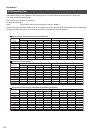
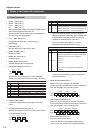
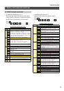
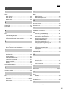
• MOTION DETECT SENSE (DCH) [JVC-1]
Returns the status data for the motion detection settings.
(Current operating mode status. The status at the time of
operations will be returned when in the timer mode.)
MOTION DETECT SENSE Return Data
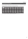
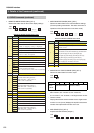
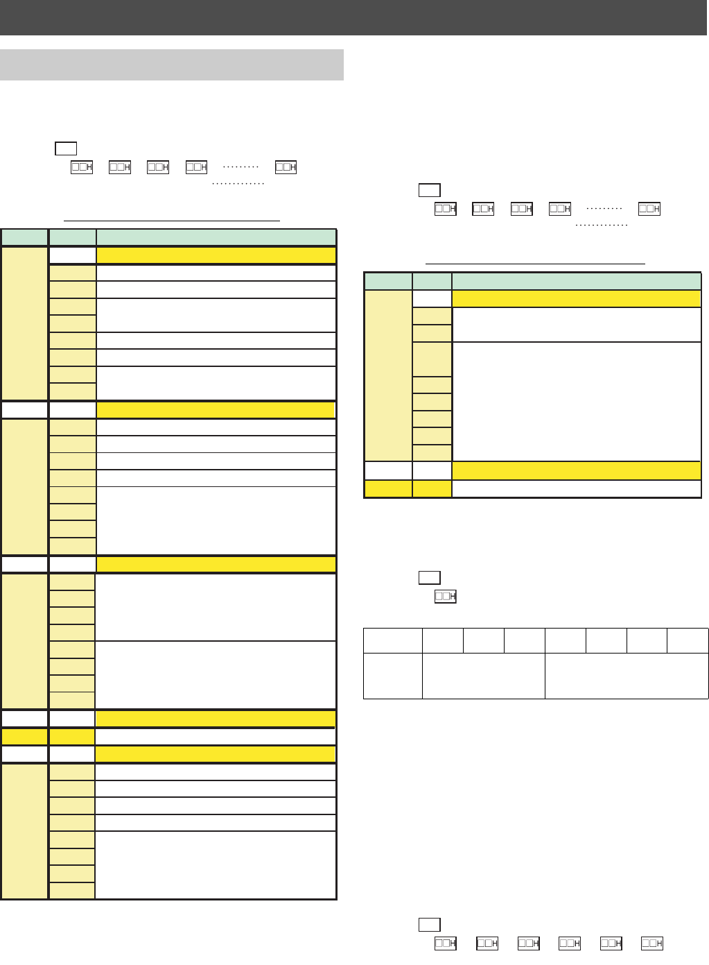
• MONITOR OUT STATUS SENSE (DEH) [JVC-1]
Returns the status data for monitor output.
* Split-screen mode
000: 9-screen, 001: 4-screen A, 010: 4-screen B,
011: 4-screen C, 101: 6-screen, 110: Single screen monitor
* Camera number
Displays the relevant camera number when a single-screen
monitor is in use. (0 to 9) Displays the top left-hand camera
number when split-screen monitors are in use.
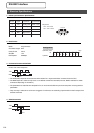
• MAC SENSE (FCH) [JVC-1]
Acquires the MAC address (6 bytes.)
3. Details of the Commands (continued)
3.4. SENS Commands (continued)
DBH
TXD
RXD
1st byte
2nd byte 3rd byte 7th byte
“1” output with auto scandisk at [ON].
Monitor Display Settings 2/7
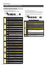
Monitor Display Settings 3/7
Monitor Display Settings 4/7 to 6/7
4 to 6
bit7 to 0 Contents the same as 3BYTE (cameras 3 to 8)
7
Automatic switch setting (camera 9):
0000: OFF, 0001: 1, 0010: 2, 0011: 3,
0100: 5, 0101: 10 (seconds)
3
Automatic switch setting (camera 2):
0000: OFF, 0001: 1, 0010: 2, 0011: 3,
0100: 5, 0101: 10 (seconds)
Automatic switch setting (camera 1):
0000: OFF, 0001: 1, 0010: 2, 0011: 3,
0100: 5, 0101: 10 (seconds)
1
Alarm detection display:
00: OFF, 01: Fixed, 10: Sequential
2
4-screen automatic switch setting:
0001: 1, 0010: 2, 0011: 3, 0100: 5, 0101: 10 (seconds)
byte No. bit No.
Not defined (fixed at “0”)
bit 7
bit 6
bit 5
bit 4
bit 3
bit 2
bit 1
bit 0
bit 7
bit 6
bit 5
bit 4
bit 3
bit 2
bit 1
bit 0
bit 7
bit 6
bit 5
bit 4
bit 3
bit 2
bit 1
bit 0
bit 7
bit 6
bit 5
bit 4
bit 3
bit 2
bit 1
bit 0
Monitor Display Settings 1/11
“1” output with VGA output at [ON].
Border color:
00: Black, 01: Light gray, 10: Gray, 11: Bright gray
Not defined (fixed at “0”)
Not defined (fixed at “0”)
Not defined (fixed at “0”)
Not defined (fixed at “0”)
Not defined (fixed at “0”)
Monitor Display Settings 7/7
Not defined (fixed at “0”)
Not defined (fixed at “0”)
Not defined (fixed at “0”)
Not defined (fixed at “0”)
7 6543210
0:Live
1:PLAY
Split-screen mode* Camera number*
DCH
TXD
RXD
1st byte
2nd byte 3rd byte 9th byte
bit 7
bit 6
bit 5
bit 4
bit 3
bit 2
bit 1
bit 0
Motion Detection Settings 2/9 to 9/9
2 to 9
bit7 to 0 Contents the same as 1BYTE (cameras 2 to 9)
1
Operation setting (camera 1):
00: OFF, 01: ON
Detection sensitivity (camera 1):
00H: Standard, 01H: User, 02H: Entrance/Exit (high), 03H: Entrance/Exit
(low), 04H: Aisle (high), 05H: Aisle (low), 06H: Register (high),
07H: Register (low), 08H: ATM (high), 09H: ATM (low), 0AH: Lobby
(high), 0BH: Lobby (low), 0CH: Gate (high), 0DH: Gate (low),
0EH: Parking lot (high), 0FH: Parking lot (low), 10H: Low lighting (high),
11H: Low lighting (low), 12H: Elevator, 13H: Counter
byte No.
bit No.
Motion Detection Settings 1/9
DEH
TXD
RXD
FCH
TXD
RXD
1st byte
2nd byte 3rd byte
4th byte
5th byte 6th byte