


15
Installation and Preparation
\
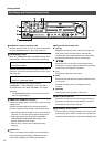
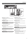
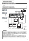
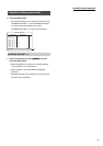
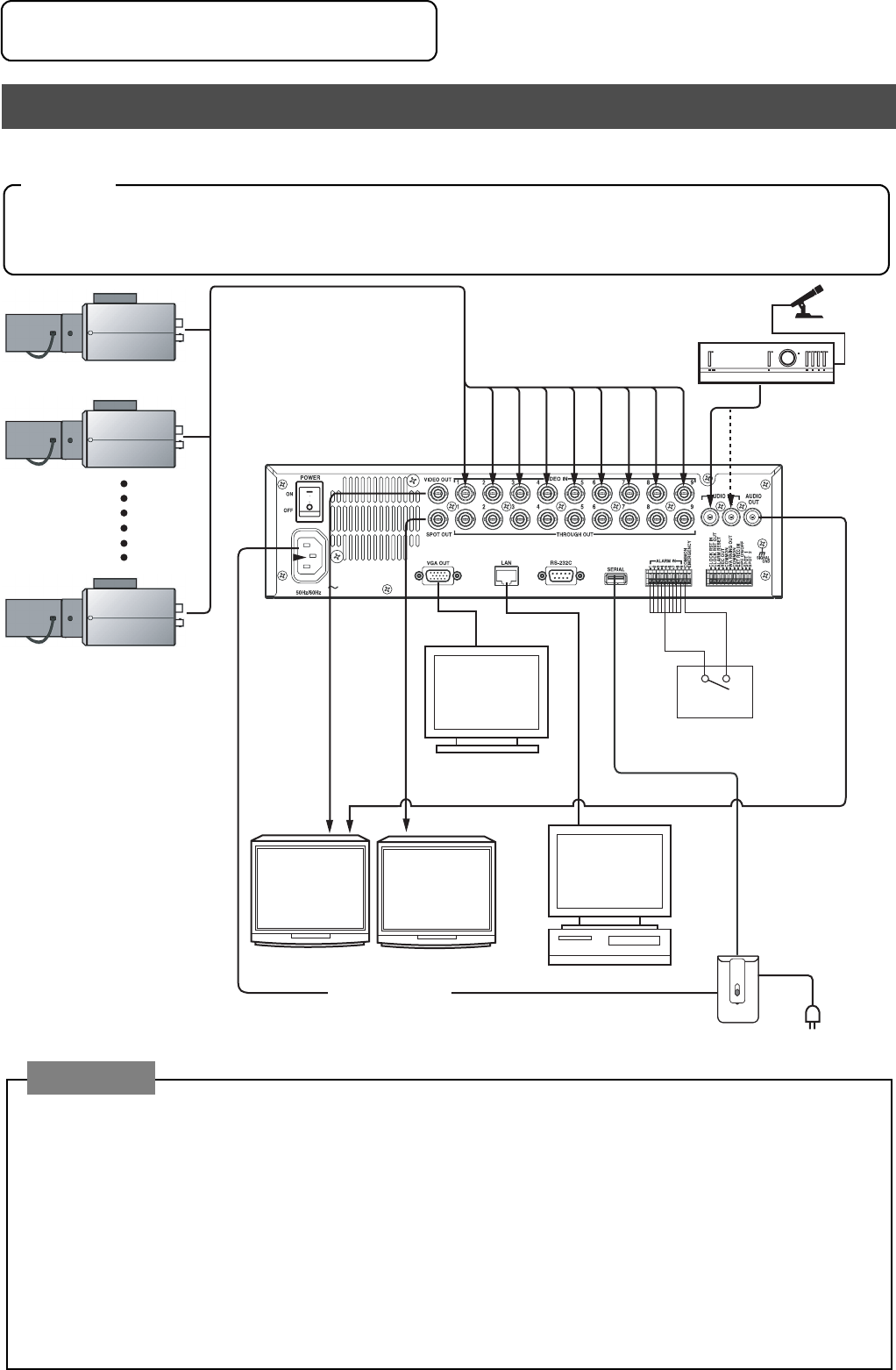
Connection with up to 9 cameras is possible with VR-509’s switcher.
System Connection (When connecting 9 Cameras)
<Example>
• Perform recording/playback by connecting to 9 cameras.
• Checking recorded images at Monitor.
• Execution of alarm recording upon detecting alarm signals.
AC IN 220V - 240V
Alarm
Microphone
Amplifier
VGA Monitor
Computer
Monitor 1
Monitor 2
UPS
AC 220 V - 240 V
50 Hz/60 Hz
AC 220 V - 240 V output
AC 220 V - 240 V
[AUDIO
IN]
[VIDEO IN]
[VIDEO IN]
Control
(Communication)
Terminal
Camera 1
Camera 2
Camera 9
Power Cord
(Supplied with this equipment)
Precautions:
• When TV video image signals other than those input by cameras are input, there are cases where live image display and
REC playback will not operate normally.
• A message stating “No VIDEO IN * * Input (E-03)” will be displayed on the on-screen when a problem occurs with image
signal input. (The number of the camera is displayed in * *). If recording is continued in this state, there is a possibility that
accurate recording will not be possible not only with the affected camera, but also with normally operating cameras. In this
case, either invalidate the input recording for which the problem occurred, or resolve the cause of the problem
immediately. (See INTRODUCTION SET - 1 on page 20.)
• Make sure that the power supply to all devices is turned off before establishing the connections.
• Make sure that the input terminals to which no cameras are connected are set to “DISCONNECT” on the menu. See
INTRODUCTION SET - 1 on page 20.)
• When a BNC connector is connected to THRU OUT, the built-in 75Ω end terminal will become OPEN. Connect the last
device to the end terminal at 75Ω.
• When connecting other equipment, make sure the relevant instruction manuals are read thoroughly beforehand.
• See the section on Connecting to a PC on page 65 for details on establishing connections with personal computers.
Installation and Preparation