


17
•••••••••••••••••••••••••••••••••••••••••••••••••••••••••••••••••••••••••••••••••••••••••••••••••••••••••••••••••••
Connections
ENGLISH
Connections
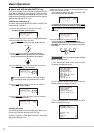
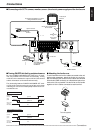
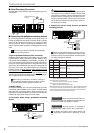
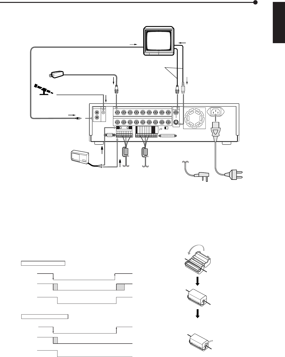
■ Connecting with CCTV camera, monitor, sensor ,the electric power supply and the ferrite core
CLOCK ADJ
REC
POWER ON
POWER OFF
ALARM OUT
MODE OUT
CALL OUT
CALL OUT GND
DC 5V OUT
MAX 30mA
1
MIC
IN
OUT
23456789
1
RS-232C
234
123456789
CAMERA INAUDIO
CAMERA OUT
ALARM IN
5678
RESET
9
ON OFF
SCSI
SCSI
TERMINATION
Y/C
OUT
VIDEO
GND GND
GND
GND
GND
MONITOR
To
VIDEO OUT
or
S(Y/C) OUT
terminal
To AUDIO OUT terminal
To peripheral loudspeaker or monitor
through AUDIO IN terminal
One of either codes should
be connected.
To CAMERA IN 1
terminal
CAMERA #1
To S(Y/C) IN
terminal
•••
MICROPHONE
SENSOR #1
To GND
terminal
To ALARM IN terminal
corresponds to the
CAMERA #.
POWER CORD
To MIC terminal
•
•
•
Up to 9 cameras
for U.K
for the Continent
Ferrite core
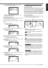
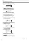
■ Turning ON/OFF this Unit by peripheral source
By using POWER ON/POWER OFF terminal on I/O termi-
nals, it is possible to turn on/off this unit externally. Turning
on/off this unit is related to the output of DC 5V OUT terminal
and this information can be transferred externally.
The relationship between POWER ON/POWER OFF termi-
nal, DC 5V OUT terminal and turning on/off this unit is shown
in the diagram. Please use suitable peripheral devices to con-
nect with this unit.
Using POWER ON terminal
POWER ON
terminal
ground
0V
power off
Unit's
power
DC 5V OUT
(4.5-5.5V
Max.30mA)
DC 5V
power on
power on
shut down
boot
up
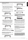
Using POWER OFF terminal
POWER OFF
terminal
0V
power off
ground
shut down
power on
Unit's
power
DC 5V OUT
(4.5-5.5V
Max.30mA)
DC 5V
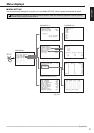
■ Attaching the ferrite core
To avoid interference from the cables connected to the unit
against other apparatus, attach the ferrite core to all ca-
bles connected to the control terminal cables and ALARM
IN terminals (GND terminals) as indicated and place it as
close to the unit as possible. Use the ferrite core to bundle
together all of the cables connected to each terminal.
Tie cables at the band
To the other apparatus