


38
•••••••••••••••••••••••••••••••••••••••••••••••••••••••••••••••••••••••••••••••••••••••••••••••••••••••••••••••••••••••••••••••••••••••••••
•
Multiplexer functions (continued)
■ Multiplexer settings
There are 3 types of camera settings: A, B and C. You can
set the cameras to be operated at each setting. It is useful
to make titles with the setting on the same menu.
Example: Set Camera CH (channel) 5 as an operated
channel on CAMERA USAGE B. The title will be “EXIT”
(the default setting is to operate camera CH 1 to 4).
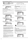
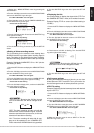
1. Press the SET UP button to display the <MENU SETTING>
menu.
2. Move the cursor (
) to MPX FUNCTIONS then turn the
SHUTTLE ring to the right.
• The <MPX FUNCTIONS> menu will appear.
<MPX FUNCTIONS>
@CAMERA USAGE
CAMERA SETTING
SPLIT SCREEN SETTING
SPLIT P.GRADE
A
SHARP
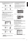
3. Turn the JOG dial to move the cursor to CAMERA SETTING
and turn the SHUTTLE ring to the right.
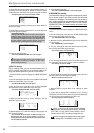
• The <CAMERA SETTING> menu will appear. The “ ” will
appear next to the CH number of the camera if it is set to be
operated. The default setting is to operate CAMERA CH 1
to 9 for CAMERA USAGE A, 1 to 4 for CAMERA USAGE B
and 1 for CAMERA USAGE C.
Precautions related to settings
With CAMERA SETTING, at least one camera
channel must be activated for each camera op-
eration A, B and C. (Active channels are indi-
cated by “
” .) Please note that the settings
menu cannot be exited until this is done.
Set all cameras to be activated for Alarm re-
cording to be operated on the <CAMERA SET-
TING> menu.
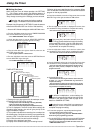
<CAMERA SETTING>
CH ABC TITLE
@
1
&&& ................
2
&&- ................
3
&&- ................
4
&&- ................
5
&-- ................
6
&-- ................
7
&-- ................
8
&-- ................
9
&-- ................
CAMERA
NUMBER
CAMERA
USAGE
PATTERN
CAMERA TITLE
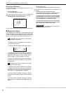
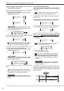
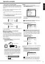
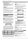
4. Turn the JOG dial to the right to move the cursor next to
CH
5
and turn the SHUTTLE ring to the right to until “ - ”
flashes.
4
&&- ................
@
5
&-- ................
6
&-- ................
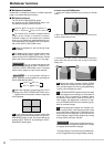
5. Turn the JOG dial to display “ ” and turn the SHUTTLE
ring to the right.
• The flashing will move to the next line.
4
&&- ................
@
5
&&- ................
6
&-- ................
INFORMATION
Complex operation settings are
possible when settings for CAMERA SETTING B
and CAMERA SETTING C are made at the same
time. For example, by pre-programming the opera-
tion, the unit can be made to switch and execute an
operation to match the situation through the CAM-
ERA USAGE setting in the <MPX FUNCTIONS>
menu. In addition, an easy-to-understand surveil-
lance system can be constructed by adding titles to
the camera settings.
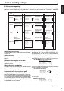
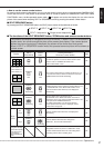
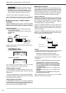
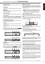
6. Turn the SHUTTLE ring to the right to flash the first column
of the TITLE setting.
4
&&- ................
@
5
&&- ................
6
&-- ................
7. Turn the JOG dial to display “E” and turn the SHUTTLE ring
to the right to move the flashing to next column.
4
&&- ................
@
5
&-- E...............
6
&-- ................
4
&&- ................
@
5
&&- EXIT............
6
&-- ................
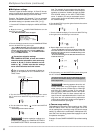
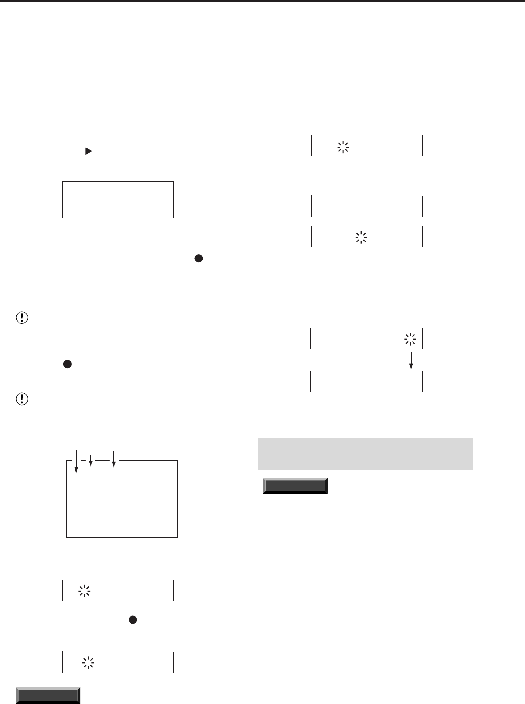
8. Repeat Steps 6 and 7 to input “EXIT” .
• Turning the SHUTTLE ring to the left while inputting will
erase the character. To exit the TITLE column, move the
flashing to the right end, then turn the SHUTTLE ring to the
right to fix title setting.
• To continue title setting, turn the JOG dial to move the cursor
to desired camera CH.
4
&&- ................
@
5
&&- EXIT............
6
&-- ................
4
&&- ................
@
5
&&- EXIT............
6
&-- ................
9. To finish setting, turn the SHUTTLE ring to the left or press
the SET UP button.
• You cannot exit the menu till you fix title setting (if one of
the columns of the TITLE is flashing). To fix the setting please
refer to step 8 above.
INFORMATION
A warning appears when the unit
records while there is no input signal in the desig-
nated camera channel. (Please refer to “Warnings
and CALL OUT output” on page 75 for more de-
tails.) In addition, please select “invalid” in the <CAM-
ERA SETTING> menu for those cameras with no
input. If the unit is operated without this “invalid” set-
ting, there are rare occasions during split-screen
viewing when image from another screen appear in
a channel without an input signal.
♦ Camera usage setting
This setting is to choose the camera setting on the <CAM-
ERA SETTING> menu. You can make good use of this
unit by making timer recordings using the Camera usage
setting. For details of the combination of Multiplexer func-
tions and Timer recording, please refer to pages 41 and 42
for operation examples.
Example: Choose CAMERA USAGE B (the default setting
is “A”).