74
••••••••••••••••••••••••••••••••••••••••••••••••••••••••••••••••••••••••••••••••••••••••••••••••••••••••••••••••••••••••
Glossary
OTHERS
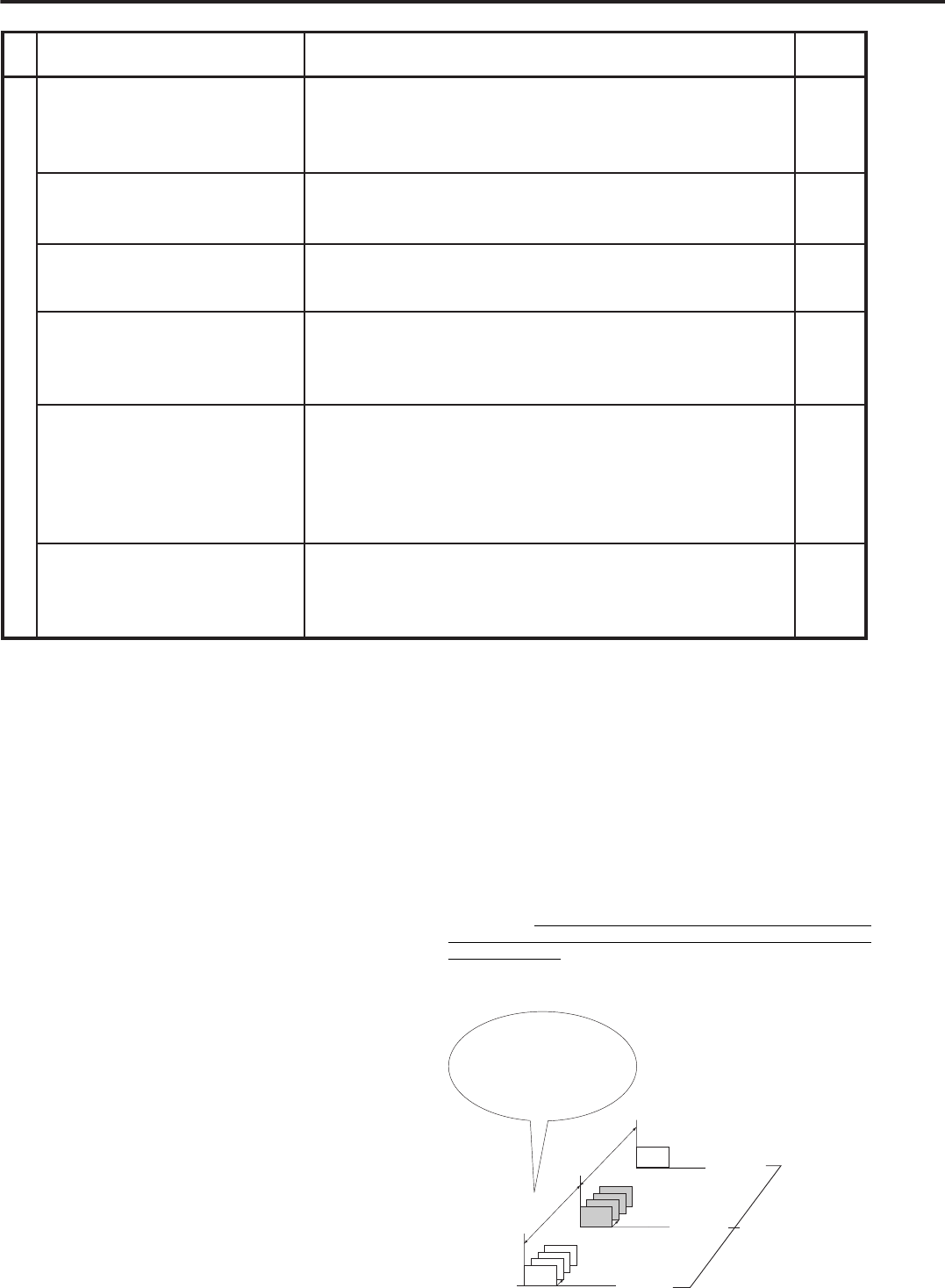
PagePlease consult the followingDescription of problem
The unit will not respond to PC
control.
The DEVICE CHECK menu
does appear when power is
turned on.
The unit is not detecting its
peripheral recording device(s).
Black screens are being
displayed during multi-screen
display.
Button operation is not working.
Button operation of camera
numbers is not working.
Is the RS-232C setting set correctly?
Are the unit and computer connected correctly?
Is there a defect in the connecting cable?
Is the proper connecting cable being used?
Is peripheral device’s SCSI ID setting set correctly?
Inspect the connecting cable.
Is the SCSI terminator switch on?
Have the peripheral devices been disconnected?
Are the recommended peripheral devices being used?
Operations settings have not been made, in the Camera
Operation Setting parameter of the MPX FUNCTIONS
screen. Input from cameras not displaying the “•” symbol
will appear black on the monitor.
Is the playback device indicator light blinking? Wait until the
light stays on, then start operation once more. If the light
does not stop blinking for a long period, use the RESET
button located at the back of the unit.
Is the LOCK function or the PASSWORD LOCK function in
effect? If so, please cancel the function(s).
Is the Menu screen being displayed? (Camera number
buttons cannot be used when the Menu screen is displayed.)
Is the unit currently accessing a peripheral recording device?
Check the ACCESS indicator.
8,57
57
57
57
20,51
-
8
-
-
37
6,7,8
56
10
6,7
SCSI Interface
The SCSI interface is the connection used expressly for transferring
image data between the unit and its peripheral devices. Each periph-
eral is connected to the unit in a daisy-chain configuration, and is
given a unique ID number for detection/identification by the unit.
Relation of recording operation to the number of
cameras and recording interval settings
The recording pattern of this unit is as illustrated in the diagram be-
low. Image data input from all the connected cameras is recorded
sequentially at a rate of [number of cameras x recording interval].
(Recording interval for each camera is 25F.)
For example, when four cameras are recording at intervals of 1 sec-
ond, the unit takes four seconds to receive one cycle of image data
from the cameras. When this data is played back on a single-screen,
the display is refreshed once every four seconds.
C4-2
C3-2
C2-2
C1-2
C4-1
C3-1
C2-1
C1-1
25F
4 seconds
4 seconds
12:00:00~
12:00:04~
12:00:08~
C1-3
Circuit recording interval per camera
[ recording interval x # of cameras ]
1 second x 4 cameras = 4 seconds
Examples of time displayed
during playback.
■
Glossary
Simultaneous Backup (Copying) method
In Simultaneous Backup (Copying), images input from the cameras
are recorded once on the unit’s hard disk and simultaneously copied
from the hard disk onto a removable archive/copying medium. Be-
cause images are first recorded onto the hard disk, the unit performs
well for Alarm Recording and high-quality images needs, and can use
“blank time” to backup/copy onto the separate medium. In addition,
the unit marks the end of backup recording time through the use of
the Archive Pointer.
Archive Pointer
The Archive Pointer is used to mark, on the archive medium, the com-
pletion of a backup process. For example, 100 hours of data recorded
on the unit’s hard disk is to be transferred to a medium with only 80
hours of available recording space. When the backup process is com-
pleted, the Archive Pointer will memorize the hard disk’s 80-hour mark.
When the next backup process is initiated, backup will begin at this
point.
Copying Device
The copying device is the peripheral device assigned to SCSI ID5. By
using the unit’s COPY button, this device can be made to copy (re-
store) image data recorded over a designated time frame.
Archive Device
The archive device is the peripheral device assigned to SCSI ID4,
and performs the following: backup specification using the ARCHIVE
button or Timer Program, and backing up of image data using the
Restore function in the Copy settings.
Restore
Restore is the process in which image data transferred to the periph-
eral recording device is restored on the unit’s hard disk. During the
Restore process, image data currently stored on the unit’s hard disk
is completely over-written.
/ Glossary
Troubleshooting (continued)


