


Chapter 2. TV Connections 31
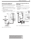
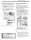
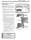
IR Emitter NetCommand® and TV
Guide On Screen
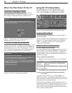
An IR emitter cable is included with the TV.
TheNetCommandsystemusesemittersconnectedto
the
IR EMITTER
jacktocontrolotherdevicessuch
asVCRs,DVDplayers,cableboxes,andsatellitereceiv-
ers.ThiscontrolsystemissharedwiththeTVGuideOn
Screensystem.
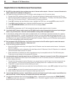
1. ConnecttheplugendofthesuppliedIRemittercable
tothe
IR EMITTER NetCommand®
jackonthe
TVbackpanel.
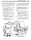
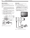
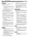
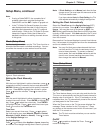
2. Runthecableforeachoftheemitterendsunder,
alongside,orovereachdevicetobecontrolledsothat
theemitterendisinfrontoftheareawheretheremote
controlsensorislocated.
3. Positiontheemitterendwiththeemitterbulbfacing
theremotecontrolsensor.Thebulbemitsinfrared
lightinacone-shapedpattern.Placethebulbfar
enoughfromthesensortoallowtheconepatternto
reachthesensor.
TheIRsensorisusuallybehindtheplasticwindow
ofthefrontdisplaypanel.Itissometimesvisible
withtheaidofaflashlightandisnormallyaroundor
squarecutoutbehindtheplastic.Ifyoucannotsee
thesensorandthedevice’sOwner’sGuidedoesnot
specifythelocation,youcanfinditbyfollowingthese
stepsusingthedevice’sremotecontrol:
a. Holdtheremoteaboutone-halfinchfromthe
frontofthedevice.Startingfromoneendofthe
displaywindowplastic,pressthe
POWER
button.
b. Ifthedevicedoesnotrespond,movetheremote
controloneinchtowardthecenterandtryagain.
c. Repeatthisuntilthedeviceresponds.
d. Notethislocationandthenstartoverfromthe
otherendofthedisplaywindowplastic,repeating
untilthedevicerespondsagain.
Theremotecontrolsensorissomewherebetween
thesetwopositions.Thisisusuallyenoughaccu-
racyforplacementoftheIRemitters.
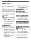
Withsomedevices,theemitterworksbetter
facingdownwardfromthetopofthedevice.
Experimentifneeded.
4. Securetheemitterendsinplaceusingdouble-sided
tape.
5. Placeanyunusedendsbehindthedevicestoprevent
straysignalsfromreachingtheIRsensors.
1$%7*
"6%*0
"6%*0
065
$0.10/&/5
*/165
.0/*503
065
)%.*%7*"6%*0
"/5."*/
"/5"69
*&&&
%*(*5"-
"6%*0
065
)%.*
1$%7*
7*%&0
-&'5
3*()5
-&'5
3*()5
:
1C
1S
"6%*0
-&'5
.0/0
"6%*0
3*()5
-&'5
3*()5
64&8*5)
$BCMF$"3%
$BCMF$"3%
64&8*5)
"/5$"3%501
47*%&0
7*%&0
"6%*0
-&'5
.0/0
"6%*0
3*()5
)%.*$0.1"5*#*-*5:
7*%&0JQQJQ
$0.10/&/5$0.1"5*#*-*5:
7*%&0JQQJ
%7**1$$0.1"5*#*-*5:
3&'&35008/&34(6*%&
TM
R
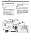
57#BDL1BOFM
%*(*5"-
463306/%
4
$)
"73FDFJWFS
0UIFS"7EFWJDF
Figure 14. Connecting IR Emitter NetCommand
*OGSPOUPGB
TJOHMFBWFSBHF
TJ[FEEFWJDF
0OUPQPGBTJOHMF
UBMMEFWJDF
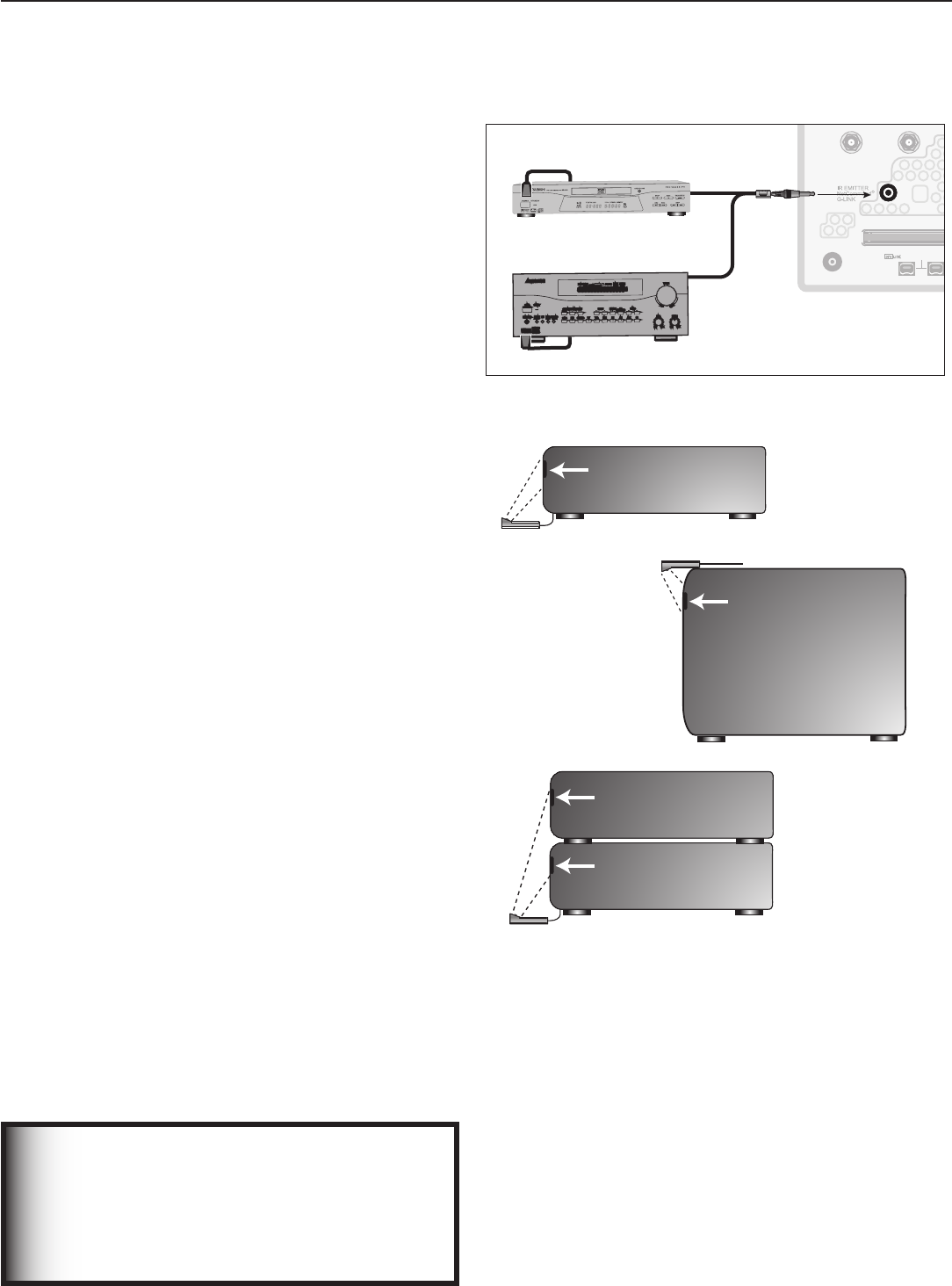
*OGSPOUTIBSFE
CZUXPBWFSBHF
TJ[FEEFWJDFT
*3TFOTPS
*3TFOTPS
*3TFOTPS
*3TFOTPS
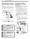
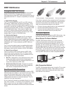
Figure 15. IR emitters so the signal can be “seen” by the
IR sensor on each device.
IMPORTANT
Position IR emitters so that each device’s
sensor “sees” the signal from only one
emitter. Otherwise, a device receiving signals
from multiple sources (remote controls, IR
emitters) may not respond at all.