22 C1696M (8/06)
USING THE JOG/SHUTTLE TO NAVIGATE THROUGH MENUS
There are two ways to return to a previous, or higher level, menu:
• Turn the jog (inner dial) to the right or left until you select the Back icon on the screen, and then press the
Enter/Shift key .
• Turn the shuttle (outer ring) counterclockwise.
The icon path at the top of the menu bar tells you which menu icons you selected to arrive at your current location. This lets you know how deep
within the menu structure you are and how many levels there are to reach the main menu. Most functions are no more than one or two levels
deep. For example, in the figure below, you would need to return one level to reach the main menu from the Search/Export menu.
Figure 13. Sample Icon Path
USING THE CONTROL PAD TO ENTER CHARACTERS
The DVR5100 can be configured and operated from the Control Pad, KBD5000 keyboard, USB PC keyboard, and Remote Client. This section
describes how to use the DVR5100 Control Pad to enter characters in text fields.
To enter characters using the Control Pad:
1. Select a field that supports character entry, for example a name field or IP address field.
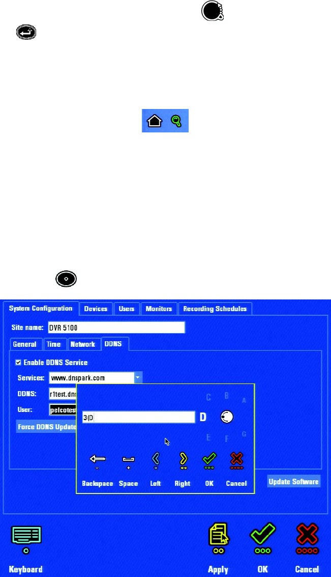
2. Press the blue function key to display the on-screen keyboard.
Figure 14. On-Screen Keyboard


