28 C1696M (8/06)
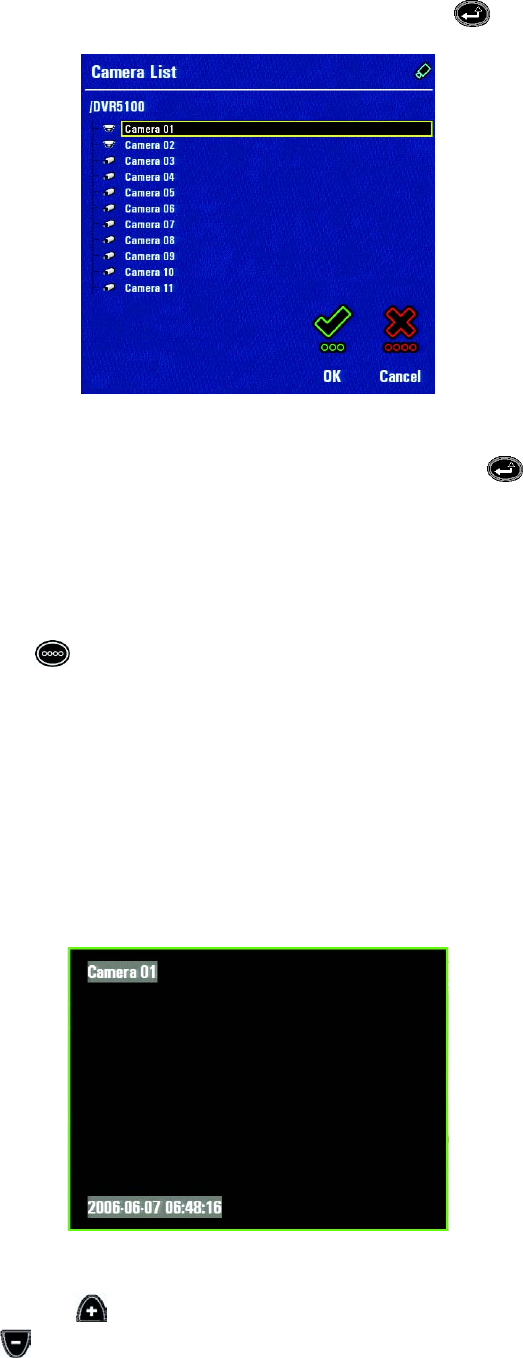
4. If it is not already selected, navigate to the Select Camera icon, and then press Enter/Shift . The Camera List appears.
Figure 25. Camera List
5. Use the joystick or the jog (inner dial) to select a camera from the list, and then press Enter/Shift . Video from the camera is displayed
in the selected video pane.
NOTE: A red slash through a camera icon indicates that it is not currently available for display.
To display a specific camera in full-screen mode:
1. Navigate to the video pane displaying the desired camera.
2. Press the red function key until the display changes to a single pane.
MOVING THROUGH THE CAMERA SEQUENCE
Although a camera is displayed in a specific video pane, you can quickly cycle through the list of cameras in sequence.
To sequence through the list of cameras:
NOTE: The instructions in this manual refer to the DVR5100 Control Pad. An optional KBD5000 keyboard or USB PC keyboard and mouse also can
be used to operate the DVR5100 instead of the Control Pad. Refer to Understanding DVR Controls and Menus on page 13 for alternate keystrokes
if you any of these devices.
1. In the live video mode, use the joystick to select a video pane. A green border surrounds the video pane.
Figure 26. Displaying a Camera in a Video Pane
2. On the Panel Keypad, press Plus to view the next camera in the sequence in the video pane. To view video for the previous camera in
the list, press Minus .


