


C1695M (8/06) 19
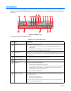
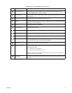
Audio Inputs 3 and 4 Audio inputs 3 and 4 are for channel 9 and 10. For information about audio inputs for a 4 or
8 channel DVR5100, refer to item 3 in this table.
Video Inputs 9–16 Camera inputs 9–16 for a 16 channel DVR. The rear panel layout might be different for the 4 and
8 channel DVR.
Looping Video Outputs 9–16 One looping video output is provided for each camera input.
USB 2.0 Two USB 2.0 ports are provided for connecting an USB device, such as an optional KBD5000, USB
PC keyboard, or USB storage media.
RJ-45 Gigabit Ethernet RJ-45 port (1000BaseT).
3.5 mm Audio Jack Provides mono audio output.
Analog Video Output Output connector, for sending video to an analog device such as an NTSC or PAL monitor.
DB15 VGA VGA connector for connecting a primary VGA monitor.
S-Video S-Video connector for connecting a primary monitor.
Relays 3–4 One relay is provided for every 4 channels. Relay output 3 and 4 for channel 9 and 10 are provided
for a16-channel DVR. Relays are numbered from top to bottom.
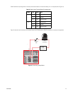
RJ-45 Port Supports an RS-422 port for connecting a PTZ device.
Alarms 9–12 and 13–16 One programmable alarm input is provided for each video input. Alarm inputs for video input 9–16
are organized as follows:
• Alarm input 9–12 for video 9–12
• Alarm input 13–16 for video input 13–16
Alarms are numberd from the top left through the bottom right. The rear panel layout might be
different for the 4 and 8 channel DVR.
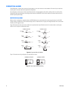
SEQ Monitor Use the SEQ output connector to connect a spot monitor to display video sequentially from each
video input.
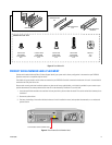
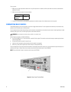
Table A. Parts of the DVR5100 Back Panel (Continued)
Item Part Description
ᕫᕻ
ᕫᕼ
ᕫᕽ