


24 C1695M (8/06)
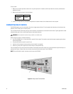
To set up audio:
1. Make sure your audio input device matches the 1 Vp-p line input level. If the device and line input levels do not match, audio distortion
problems may occur.
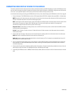
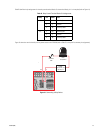
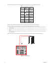
2. Make sure the audio connector is wired as follows:
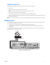
3. Connect a line input device or preamplified microphone to the audio connector for the video channel on the rear panel.
CONNECTING RELAY DEVICES
The DVR5100 supports up to four relay devices. Use them to trigger external devices. The unit supports both momentary and continuous relay
operation, either normally open or normally closed.
You can operate the relay interactively, during an active connection, or automatically to coincide with certain events. Typical applications include
activating a door, gate, or lock, or switching on lights or other electrical devices.
When wiring the connector, consider the following:
• Use 16 to 26 AWG (0.14 to 1.5 mm
2
) wire that is rated for 250 V or higher. The insulation must be thick enough to protect against electro-
static discharge (ESD).
• Strip the relay control wire to 0.3 inches (7.6 mm).
• Insert the wire far enough into the connector so that the metal is not exposed.
• When using a relay with a higher load, install an external, more powerful relay.
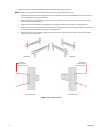
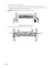
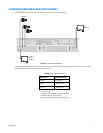
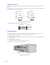
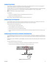
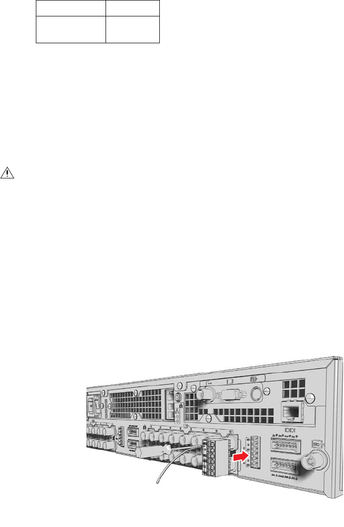
The unit includes two six-pin relay control terminal blocks. These blocks have tension clamps. Use a small screwdriver to open the clamp for a
particular lead. Figure 14 shows how to wire the relay control terminal block and connect it to the DVR5100.
NOTE: The terminal block is keyed. It attaches only one way to the DVR5100.
Figure 14. Relay Control Terminal Block
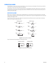
Connector Tip Signal high
Connector
Sleeve
Common
WARNING: Do not exceed the maximum ratings: 30 VDC, 2 A; 125 VAC, 0.5 A.