


18 C1695M (8/06)
Connections
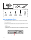
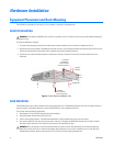
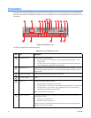
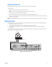
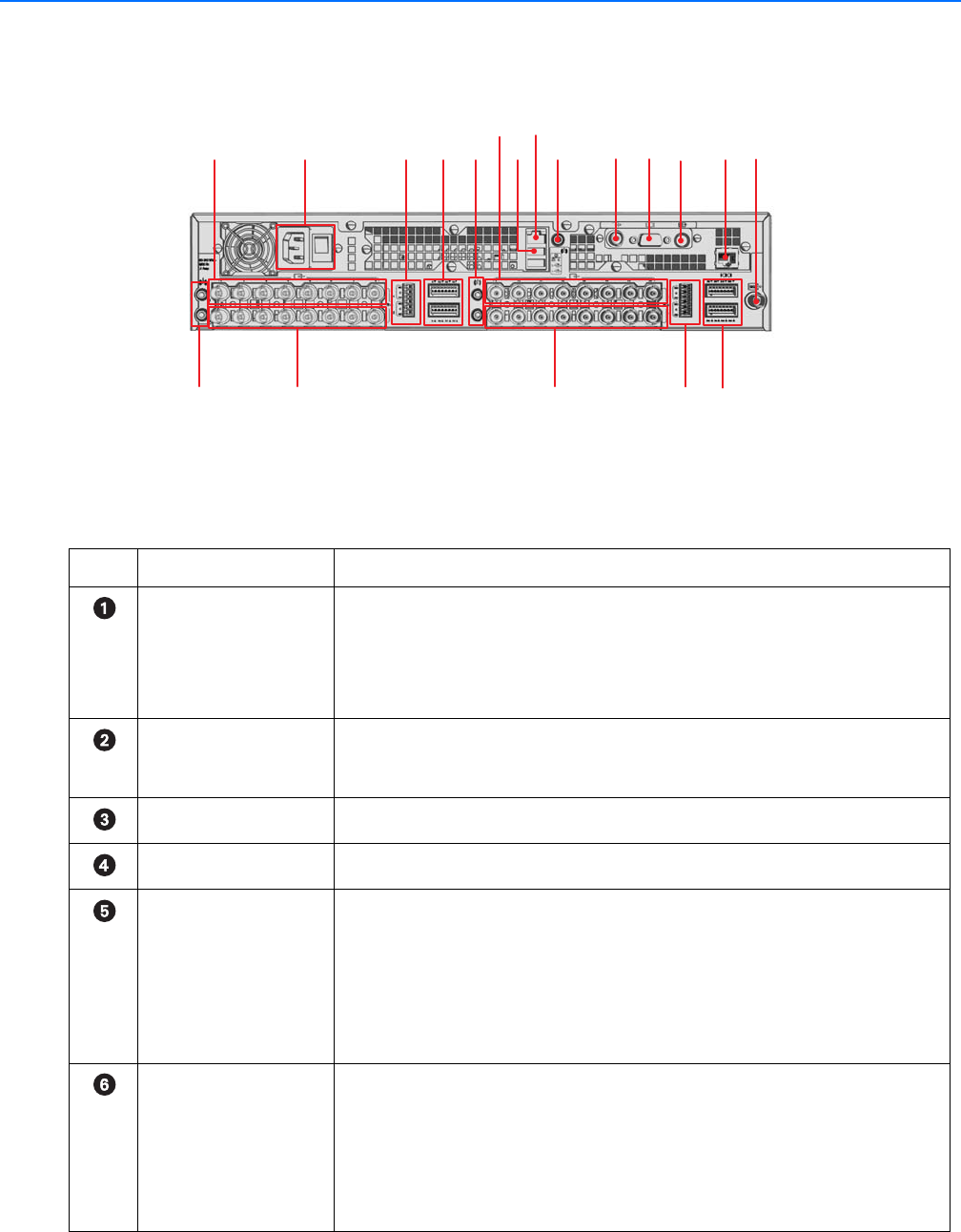
Familiarize yourself with the DVR5100 back panel before connecting any equipment to the unit. The following figure shows the DVR5100 back
panel for the 16-channel DVR. The DVR5100 is available as 4, 8, or 16-channel DVR. In this case, the back panel of the 4 and 8 channel units is a
little different.
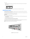
Figure 11. DVR5100 Rear Panel
The following table describes the DVR5100 back panel.
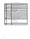
Table A. Parts of the DVR5100 Back Panel
Item Part Description
Audio Inputs 1 and 2 Audio inputs are assigned as follows:
• Two audio inputs (1 and 2 for video input 1 and 2, respectively) are provided for a 4 and
8-channel DVR.
• Four audio inputs (1 and 2 for video input 1 and 2 and audio input 3 and 4 for video input 9
and 10, respectively) are provided for a 16-channel DVR.
Video Inputs 1–8 Camera inputs 1–8 for a 16 channel DVR. The 4 channel DVR provides camera inputs 1–4 and an
8 channel DVR provides camera inputs 1–8. The rear panel layout might be different for the 4 and
8 channel DVR.
Looping Video Outputs 1–8 One looping video output is provided for each camera input.
AC Power Connector Power.
Relays 1–2 One relay is provided for every 4 channels:
• One relay output is provided for a 4-channel DVR.
• Two relay outputs (1, 2 for channels 1 and 2, respectively) are provided for an 8-channel DVR.
• Four relay outputs (1, 2 for channels 1 and 2, respectively and 3, 4 for channel 9 and 10,
respectively) are provided for a16-channel DVR.
Relays are numbered from top to bottom.
Alarms 1–4 and 5–8 One programmable alarm input is provided for each video input. Alarm inputs for video input 1–8
are organized as follows:
• Alarm input 1–4 is for video 1–4
• Alarm input 5–8 for video input 5–8
Alarms are numberd from the top left through the bottom right. The rear panel layout might be
different for the 4 and 8 channel DVR.
ᕦᕧ
ᕩ
ᕡ
ᕣ
ᕢ
ᕥᕤ
ᕨ
ᕫᕾ
ᕫᕵ
ᕫᕶ
ᕫᕷ
ᕫᕸ ᕫᕹ
ᕫᕺ
ᕫᕻ
ᕫᕼ
ᕫᕽ