


C1695M (8/06) 25
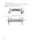
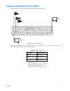
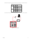
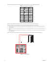
Table D identifies the pin assignments for the relay control terminal blocks. On the terminal block, pin 1 is the top lead (refer to Figure 14).
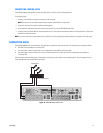
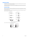
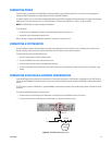
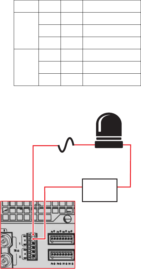
Figure 15 shows how to wire the relay with its power source to the DVR5100 (refer to Table D for the specific connector pin assignments).
Figure 15. Connecting a Relay Device
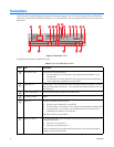
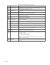
Table D. Relay Control Terminal Blocks Pin Assignments
Relay Pin Label Lead
1, 3 1 NO Normally Open
2 C Common
3 NC Normally Closed
2, 4 4 NO Normally Open
5 C Common
6 NC Normally Closed
LOAD:
LIGHT/SIREN
EXTERNAL
FUSE
NO
C
POWER
MAX: 30 VDC, 2 A
125 VAC, 5 A