


26 C1695M (8/06)
CONNECTING ALARMS
The DVR5100 offers 16 alarm inputs for external signaling devices, such as door contacts or motion detectors. Each alarm input can be either
normally open or normally closed, either supervised or unsupervised.
Once configured, an alarm input can invoke many different activities, including triggering a relay device, sending an alert to a security office,
changing the video recording settings, and storing pre-alarm video to the DVR5100. You can connect switches or contacts directly to the unit
without a separate power supply.
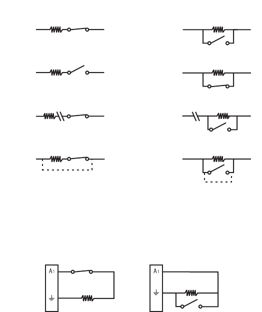
SUPERVISED ALARMS
When an alarm is configured as a supervised alarm, the DVR5100 maintains a constant electrical current through the alarm circuit (5.0 VDC,
10 kΩ), including a 10 kΩ resistor. If the resistance changes, due to an electrical short or a bypass, the voltage fluctuates from its normal state.
Therefore, the unit triggers an alarm.
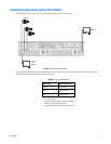
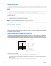
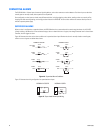
Figure 16 illustrates the alarm and no alarm conditions of a supervised alarm input. Whether the alarm is normally closed or normally open,
neither a cut nor a bypass can defeat these alarms.
Figure 16. Supervised Alarm Conditions
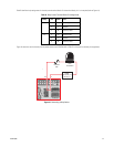
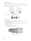
Figure 17 illustrates the wiring configuration for supervised alarm inputs.
Figure 17. Supervised Alarm Input Wiring
NORMALLY OPEN
NORMALLY CLOSED
ALARM
GND
+V
+V
ALARM
GND
+V
+V
ALARM
GND
CUT
NO ALARM
GND
ALARM
GND
+V
+V
+V
+V
ALARM
GND
BYPASS
CUT
BYPASS
NO ALARM
GND
ALARM
GND
10 K
Ω
10 K
Ω
10 K
Ω
10 K
Ω
10 K
Ω
10 K
Ω
10 K
Ω
10 K
Ω
NORMALLY CLOSED NORMALLY OPEN
10 K
Ω
10 K
Ω