


C1695M (8/06) 27
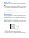
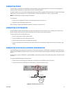
UNSUPERVISED ALARMS
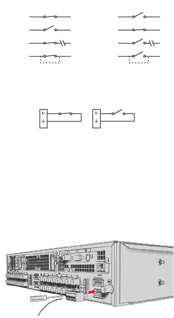
When an alarm is configured as an unsupervised alarm, the DVR5100 triggers an alarm only when the normal alarm state (open or closed)
changes.
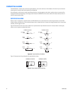
Figure 18 illustrates the alarm and no alarm conditions of an unsupervised alarm input. A normally closed alarm input can be defeated with a
bypass. A normally open input can be defeated with a cut.
Figure 18. Unsupervised Alarm Conditions
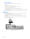
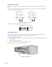
Figure 19 illustrates the wiring configuration for unsupervised alarm inputs.
Figure 19. Unsupervised Alarm Input Wiring
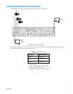
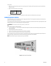
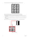
ALARM CONNECTIONS
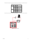
The unit includes four eight-pin alarm terminal blocks. These blocks have tension clamps. Use a small screwdriver to open the clamp for a
particular lead. Figure 20 shows how to wire the alarm terminal block and connect it to the DVR5100.
When wiring the connector, consider the following:
• Use 20 to 28 AWG (0.08 to 0.5 mm
2
) wire that is rated for 250 V or higher. The insulation must be thick enough to protect against electro-
static discharge (ESD).
• Strip the alarm wire to 0.31 inches (8 mm).
• Insert the wire far enough into the connector so that the metal is not exposed.
The terminal block is keyed. It attaches only one way to the DVR5100.
Figure 20. Alarm Terminal Block
NORMALLY OPEN
NORMALLY CLOSED
ALARM
GND
+V
+V
ALARM
GND
+V
+V
NO ALARM
GND
ALARM
GND
+V
+V
+V
NO ALARM
GND
CUT
BYPASS
CUT
NO ALARM
GND
NO ALARM
GND
+V
BYPASS
ALARM
GND
NORMALLY CLOSED NORMALLY OPEN