


12
1. CIRCUIT BLOCK
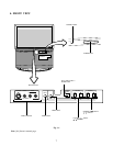
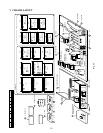
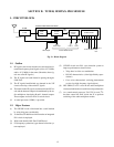
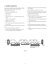
Fig. 2-1 Block diagram
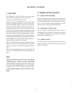
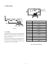
1-1. Outline
(1) RF signals sent from an antenna are converted into in-
termediate frequency band signals (video: 45.75 MHz,
audio: 41.25 MHz) in the tuner. (Hereafter, these sig-
nals are called IF signals.)
(2) The IF signals are band-limited in passing through a
SAW filter.
(3) The IF signals band-limited are detected in the VIF
circuit to develop video and AFT signals.
(4) The band-limited IF signals are detected in the SIF cir-
cuit and the detected output is demodulated by the au-
dio multiplexer, developing R and L channel outputs.
These outputs are fed to the A/V switch circuit.
(5) A sound processor (S.PRO.) is provided.
1-2. Major Features
(1) The VIF/SIF circuit is fabricated into a small module
by using chip parts considerably.
(2) As the tuner, EL466L that which contains an integrated
PLL circuit is employed.
(3) Wide band double SAW filter F1802R used.
(4) FS (frequency synthesizer) type channel selection sys-
tem employed.
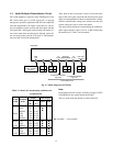
EL466L
Tuner
RF AGC
IF/MTS/S.PRO Module MVUS34S
SIF
output
Sound
Multiplex
Circuit
SAW
Filter
VIF/SIF
Circuit
S.PRO Circuit
AFT output
TP12
Video output
To A/V switch circuit
TV
R-OUT
TV
L-OUT
C-IN
R-IN L-IN
R-OUT
L-OUT
(L+R)
-OUT
C-OUT
(5) VIF/SIF circuit uses PLL sync detection system to
improve performances shown below:
• Telop buzz in video over modulation
• DP, DG characteristics (video high-fidelity repro-
duction)
• Cross color characteristic (coloring phenomenon
at color less high frequency signal objects)
(6) HIC SBX1637A-22 is used in the audio multiplexer
circuit to minimize the size with increased performance.
(7) As a sound control processor, TA1217N is used. I
2
C-
bus data control the DAC inside the IC to perform
switching of the audio multiplexer modes.
SECTION II: TUNER, IF/MTS/S. PRO MODULE