


98
6. CONVERGENCE OUTPUT CIRCUIT
6-1. Outline
This circuit current-amplifies digital convergence correction
signal at output circuit, and drives by convergence yoke to
perform picture adjustment.
Digital convergence output signal 6ch adjustment is done.
(H-R/G/B) (V-R/G/B)
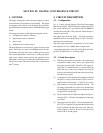
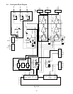
6-2. Circuit Description
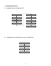
6-2-1. Signal flow
Signal which is corrected by digital convergence, is output to
P708 (V, H R/G/B);
is input to Q751 (V) R/G/B, and is output to P713, P714 and
P715;
is input to Q752 (H) R/G/B, and is output to P713, P714 and
P715.
6-2-2. Over current protection circuit
All currents of Power supply, -15V, +15V and +30V are de-
tected to protect CONV-OUT IC from damage due to output
short of CONV-OUT.
Current value: Normal ± 15V approx. 700mA
+30V approx. 200mA
Detecting curren ±15V approx. 1.8A
or more
+30V approx. 700mA or more
protecting operation
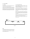
6-2-3. Pump-up source
CONV-OUT IC Q752 (H)
Pin 10 (+15V/H, PV)
Pin 5 (+30V)
By HD input signal, pump-up is done only in horizontal re-
tracing time.
6-2-4. CONV-OUT mute
In power-on operation, transistors Q765 and Q766 are made
turned ON, and –15V is applied to pin 3 of CONV-OUT IC.
These cause mute operation on CONV-OUT.
6-2-5. Operation of IC
1) Q764 (TC74HC4050AP)
Sync signal which is input from P711 1 VD, 2 HD, is,
through buffer, supplied to digital convergence P708.
2) 3-terminal source
Q754 (+5V) Q755 (+9V) Q756 (-9V)
Source for digital convergence
3) Q767 (TC4066BP)
P711 4 SDAM, 5 SCLM : microcomputer. Busline, through
Q767, is input to Digital Convergence P709, and is controlled.
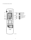
4) To adjust from outside of digital convergence :
Put adjusting jig into 6P socket of P720. Iscs turns from H to
L, switch of Q767 is changed over. Then busline from mi-
crocomputer is cut off.
P720 3 SCLU, 4 SDAU
Controlled by external adjusting jig.
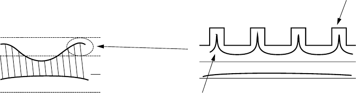
+30V
+15V
0V
-15V
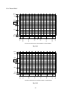
+30V
+15V
0V
-15V
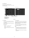
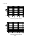
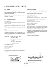
Horizontal correction wafeform
Pump-up source waveform
Pump-up
Horizontal correction waveform
Fig. 11-13