76
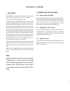
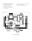
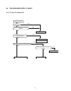
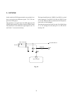
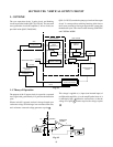
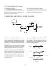
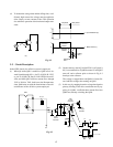
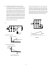
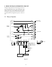
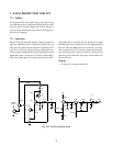
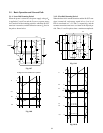
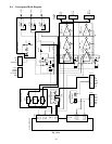
5-1-1. +210V
For the flyback period, pulses are stacked up to DC +125V
with FBT, and the voltage is rectified by D406 and filtered
by C446.
5-1-2. +35V, 12V
Pin 4 of the FBT is grounded and the shaded area of nega-
tive pulse developed for opposite period of the flyback pe-
riod is rectified, thus developing better regulation power
supply.
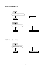
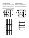
5-1-3. –27V
As a power for the DPC circuit, a negative pulse signal is
rectified by D460 and filtered with C460, thus developing
the –27V.
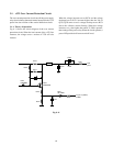
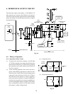
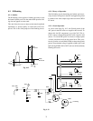
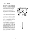
5-1-4. High Voltage
Singular rectification system which uses a harmonics non-
resonant type FBT is employed and a better high voltage
regulation is obtained, so amplitude variation of pictures
becomes low.
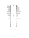
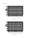
Fig. 9-16
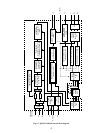
Fig. 9-17
+125V
0
10
4
7
6
2
1
0
0
For +12V
+35V
G
F
E
D
C
B
A
E
D
C
B
A
G
F
Primary
Auxiliary
Picture
tube anode
EO
ABL
EH
Pulse
Stacked
pulse of
4 block
1H
15.735KHz
Picture
tube capacitor
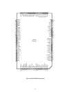
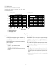
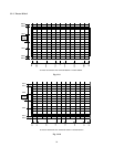
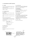
Fig. 9-18
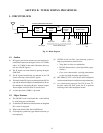
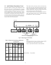
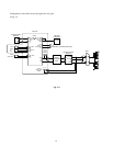
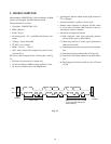
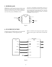
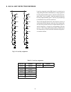
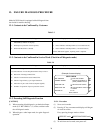
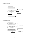
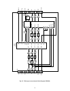
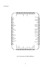
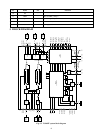
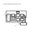
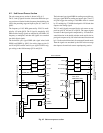
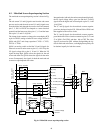
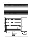
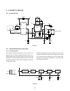
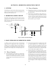
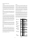
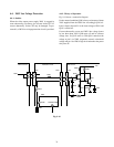
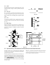
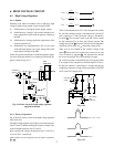
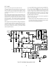
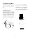
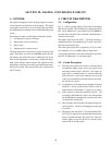
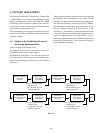
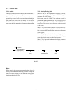
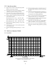
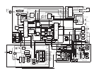
5-2. Operation Theory of the Harmonic Non-Resonant System and Tuned Waveforms
The high voltage coil is of film multi-layer winding type
and the coils are isolated into seven blocks. Each block is
connected through a diode.
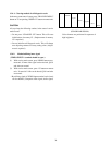
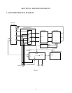
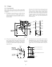
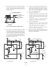
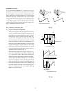
The basic operation is described in the case of 4 blocks con-
struction for simplification. Positive or negative pulse deter-
mined by stray capacitance of each coil develops at terminal
points ( A , B , C , D , E , F , G ) of each coil as shown in Fig. 9-
18, and these pulses are stacked as shown, thus developing
the high voltage.
Moreover, a capacitance between the internal and external
coatings of the picture tube works as a smoothing capacitor.
Focus voltage is obtained at point EO.