


13
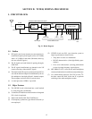
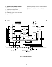
1-3. Audio Multiplex Demodulation Circuit
The sound multiplex composite signal FM-detected in the
PIF circuit enters pin 12 of HIC (hybrid IC) in passing
through the separation adjustment VR RV2 and amplified.
After the amplification, the signal is split into two: one en-
ters a de-emphasis circuit, and only the main signal with the
L-R signal and a SAP signal removed enters the matrix cir-
cuit. At the same time, the other passes through various fil-
ters and trap circuits, and the L-R signal is AM-demodu-
lated, and the SAP is FM-demodulated.
Then, both are fed to the matrix circuit. At the same time,
each of the stereo pilot signal fH and the SAP pilot signal
5fH is also demodulated to obtain an identification voltage.
With the identification voltage thus obtained and the user
control voltage are used to control the matrix.
The audio signals obtained by demodulating the sound mul-
tiplex signal develop at pin 10 and 11 of HIC and develop
the terminals of 12 and 14 of the module.
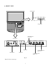
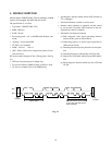
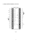
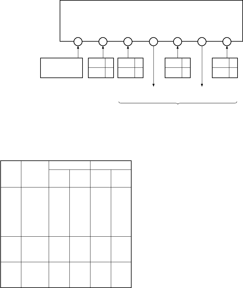
MVUS34S
MPX
Out
DAC-out1
(SURR ON/OFF)
DAC-out2
(RFSW)
TV
R-Out
TV
L-Out
9
10
11
12 13 14
15
Stereo 0V
SAP 0V
OFF 0V
Other 5V
Other 5V
ON 9V
RF1 0V
RF2 9V
To AV select circuit
Monitor the input
pin for multiplex
sound IC
TV waveform detection
output (R)
TV waveform detection
output (L)
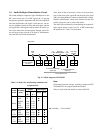
Fig. 2-2 Block diagram of MVUS34S
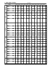
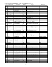
Table 2-1 Matrix for broadcasting conditions and
reception mode
Broad- Switching
Output OSD display
casted mode
12 pin 14 pin
Stereo SAP
(R) (L)
Stereo STE R L
•
–
SAP R L
•
–
MONO L+R L+R
•
–
Mono STE L+R L+R – –
SAP L+R L+R – –
MONO L+R L+R – –
Stereo STE R L
••
+ SAP SAP SAP
••
SAP MONO L+R L+R
••
Mono STE L+R L+R –
•
+ SAP SAP SAP –
•
SAP MONO L+R L+R –
•
Note:
Of the mode selection voltages, switching voltages for STE,
SAP, MONO do not output outside the module.
They are used inside the module to control the BUS.
•
: Available, – : Not available