77
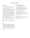
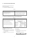
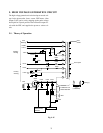
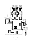
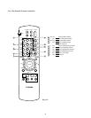
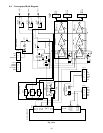
6. HIGH VOLTAGE CIRCUIT
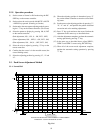
6-1. High Voltage Regulator
6-1-1. Outline
Generally, four kinds of methods exist to stabilize a high
voltage in high voltage output circuits using the FBT:
(1) Stabilization by varying the power supply voltage.
(2) Stabilization by varying L value with a saturable reac-
tance connected in series with the primary winding of
the FBT.
(3) Stabilization by varying equivalent capacitance of the
resonant capacitor C0.
(4) Stabilization by superimposing a DC or pulse (this
varies the high voltage) on a lower voltage side of the
high voltage winding of the FBT.
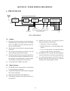
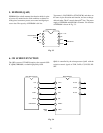
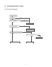
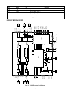
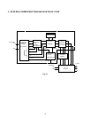
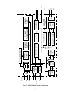
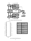
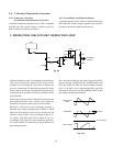
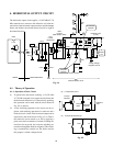
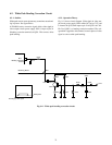
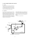
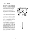
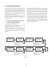
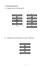
In this unit, pulse transformer is eliminated and the regula-
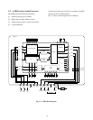
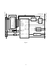
tor circuit using the method (3) is employed. The block dia-
gram is shown in Fig. 9-19.
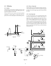
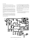
The V
CP2
developed across C2 is DC-clamped with a diode
D1 and the resultant voltage is smoothed with a diode D2
and a capacitor C3. Thus processed voltage is obtained at
the point B . This voltage is used to provide a base current
for the transistor Q1 or to flow the collector current. The
voltage at the point B decreases with the circuit impedance
and finally lowers up to a V
CE
saturation voltage of Q1.
Then, V
CP2
is not clamped by D2 with the voltage at the
point B . Since the V
CP
is expressed as a sum of V
CP1
and
V
CP2
as shown by equation 3 , V
CP
decreases by amount
the V
CP2
is decreased. This varies the high voltage.
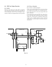
Q1 collector current is controlled by Q1 base current which
is an output of the comparison inverted amplifier. That is,
the Q1 base current is controlled by a voltage obtained by
comparing a detection voltage of the top breeder of the FBT
(9.1V) and a DC voltage of 9V.
V
CP1
= V
CP
1
V
CP2
= V
CP
2
V
CP
= V
CP2
3
C
1
+ C
2
C2
C
1
+ C
2
C2
C
1
+ C
2
C2
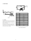
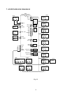
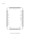
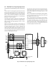
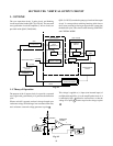
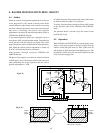
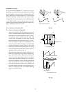
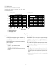
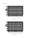
Fig. 9-21
Hotizonal
output
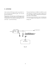
D
Y
T461
FBT
ANODE
125V
PW output
-27V
High voltage Reg.
V.
Ref.
Z450
CR-BLOCK
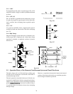
Fig. 9-19 Basic circuit for high voltage regulator
emplyed in the unit
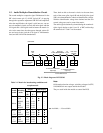
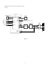
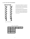
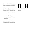
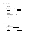
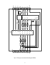
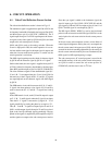
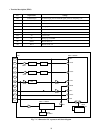
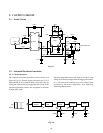
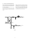
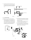
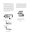
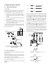
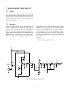
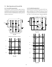
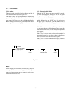
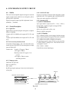
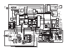
6-1-2. Theory of Operation
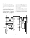
Fig. 9-20 shows a basic circuit of the high voltage regulator
used in the unit.
The high voltage regulator circuit splits a resonant capacitor
C0 to C1 and C2. thereby dividing the collector voltage (V
CP
)
of the H output transistor with C1 and C2.
Here, assume each voltage developed across C1 and C2 as
V
CP1
and V
CP1
, respectively,
each relation can be expressed by the above equations
1 ~ 3 .
Horizontal
output
C1 L
H
FBT
L
P
B
D1
C2
C3
D2
Q1
High voltag
Reg.
output amp
CS
+B
Fig. 9-20
V
CP
= V
CP1
+ V
CP2
V
CP
1
V
CP
2