


63
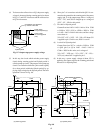
2-4. V Linearity Characteristic Correction
2-4-1. S-character Correction
(Up-and Down-ward Extension Correction)
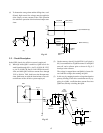
A parabola component developed across C306 is integrated
by R306 and C305, and the voltage is applied to pin 6 of
Q302 to perform S-character correction.
2-4-2. Up-and Down-ward Linearity Balance
A voltage developed at pin 2 of Q301 is divided with resistors
R307 and R303, and the voltage is applied to pin 6 of Q301
to improve the linearity balance characteristic.
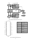
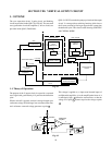
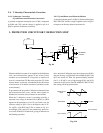
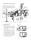
3. PROTECTION CIRCUIT FOR V DEFLECTION STOP
When the deflection current is not supplied to the deflection
coils, one horizontal line appears on the screen. If this
condition is not continued for a long time, no trouble will
occur in a conventional TV. But in the projection TV, all the
electron beams are directly concentrated at the fluorescent
screen because of no shadow mask used, and burns out the
screen instantly.
To prevent this, the stop of the V deflection is detected when
the horizontal one line occurs, and the video signals are
blanked out so that the electron beams are not emitted.
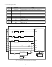
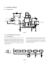
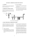
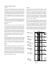
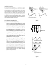
When the V deflection circuit is operating normally, a
sawtooth wave voltage is obtained across (R305), so Q350
repeats on-off operation in cycle of V sync. In this case, the
collector voltage of Q35 is set to develop less than (12V-
V
BE
(Q351)) with R352 and C350 as shown in Fig. 8-9.
Accordingly, Q351 and Q353 are continuously turned on.
As a result, diode D354 is turned off, giving no influence on
the blanking operation.
C306
2
L462+L463+L464
R350
R305
Q350
R354
C350
R352
Q351
12V
D354
D353
BLANKING
CIRCUIT
R351
9V
Q353
Q301
D350
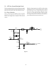
Next, when the V deflection stops, the voltage across (R305)
does not develop, so Q350 turns off, and both the Q351 and
Q353 are turned off. Then, the picture blanking terminal
pin 13 of ICA05 is set to high through R354 and D354
connected to 90V power line, BLANKING CIRCUIT ON
thus cutting off the projection tubes.
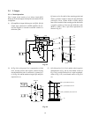
Fig. 8-10
Volttage Across
R305
Q350 BASE
Q351 Collector
Q340 V
BE
12V-V
BE
(Q341)
Fig. 8-9