


28
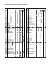
13. FAILURE DIAGNOSIS PROCEDURE
Model of N5SS chassis is equipped with self diagnosis func-
tion inside for trouble shooting.
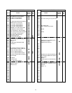
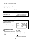
13-1. Contents to be Confirmed by Customer
Contents of self diagnosis
Contents of self diagnosis
< Countermeasure in case that phonomenon always arises >
B. Detection of shortage in BUS line.
C. Check of comunication status in BUS line.
D. Check of signal line by sync signal detection.
E. Indication of part code of microcomputer (QA01).
F. Number of operation of power protection circuit.
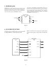
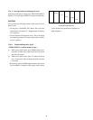
Display items and actual operation
Display items and actual operation
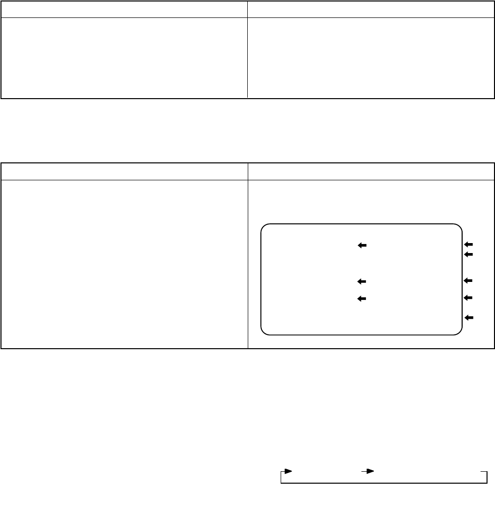
(Example of screen display)
SELF CHECK
Part coce of QA01
Number of operation of
power protection circuit
Short check of bus line
Communication check of
busline
NO. 239XXXX
POWER: 000000
BUS LINE: OK
BUS CONT: OK
BLOCK: UV V1 V2
QV01, QV01S
E
F
B
C
D
Table 3-3
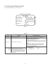
Contents of self diagnosis
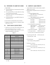
A. DISPLAY OF FAILURE INFORMATION IN NO
PICTURE (Condition of display)
1. When power protection circuit operates;
2. When I
2
C-BUS line is shorted;
Display items and actual operation
Power indicator lamp blinks and picture does not come.
1. Power indicator red lamp blinks. (0.5 seconds interval)
2. Power indicator red lamp blinks. (1 seconds interval)
If these indication appears, repairing work is required.
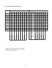
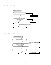
13-2. Contents to be Confirmed in Service Work (Check in self diagnosis mode)
Table 3-4
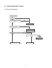
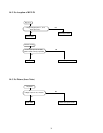
13-3. Executing Self Diagnosis Function
[CAUTION]
(1) When executing block diagnosis, get the desired input
mode (U/V BS VIDEO1, 2, 3) screen, and then enter
the self diagnosis mode.
(2) When diagnos other input mode, do again diagnosis
operation.
13-3-1. Procedure
(1) Set to service mode.
(2) Pressing “9” key on remote unit displays self diagno-
sis result on screen.
Every pressing changes mode as below.
(3) To exit from service mode, turn power off.
SERVICE mode SELF DIAGNOSIS mode