17
POP and Double Window signal processing (QY03), IC for
closed caption control (QM01), IC for WAC control (QX01),
IC for 3D-YCS (QZ01), IC for AUTOLIVE (QK06).
Differences from N5SS chassis are as follows;
1. On-screen function inside microcomputer is used. Sepa-
rate IC is not used for on-screen.
2. The microcomputer does not have the closed caption
function, but controls separate IC for closed caption.
3. The system uses two channels of I
2
C bus. One is only
for non-volatile memory.
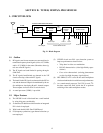
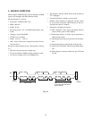
1. OUTLINE OF CHANNEL SELECTION CIRCUIT SYSTEM
The channel selection circuit in the N5SS chassis employs
a bus system which performs a central control by connect-
ing a channel selection microcomputer to a control IC in
each circuit block through control lines called a bus. In the
bus system which controls each IC, the I
2
C bus system (two
line bus system) developed by Philips Co. Ltd. in the Neth-
erlands has been employed.
The ICs controlled by the I
2
C bus system are: IC for V/C/D
signal processing (Q501), IC for A/V switching (QV01), IC for
non volatile memory (QA02), Main and sub U/V tuners (H001,
HY01), IC for deflection distortion correction (Q302), IC for
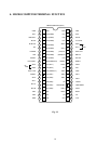
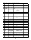
Toshiba made 8 bit microcomputer TLCS-870 series for TV
receiver, TMP87CS38N-3320 is employed for QA01.
With this microcomputer, each IC and circuit shown below
are controlled.
(1) CONTROL OF VIDEO/CHROMA/DEF SIGNAL
PROCESS IC (Q501 Toshiba TA1222AN)
• Adjustments for uni-color, brightness, tint, color
gain, sharpness and PIP uni-color
• Setting of adjustment memory values for sub-
brightness, sub-color and sub-tint, etc.
• Setting of memory values for video parameters such
as white balance (RGB cutoff, GB drive) and
gcorrection, etc.
• Setting of video parameters of video modes (Stan-
dard, Movie, Memory)
(2) CONTROL OF A/V SWITCH IC (QV01 Toshiba
TA1218N)
• Performs source switching for main screen and sub
screen
• Performs source switching for TV and three video
inputs
(3) CONTROL OF NON-VOLATILE MEMORY IC
(QA02 Microchip 24LC08BI/P)
• Memorizes data for video and audio signal adjust-
ment values, volume and woofer adjustment val-
ues, external input status, etc.
• Memorizes adjustment data for white balance (RGB
cutoff, GB drive), sub-brightness, sub color, sub
tint, etc.
• Memorizes deflection distortion correction value
data adjusted for each unit.
SECTION III: CHANNEL SELECTION CIRCUIT
2. OPERATION OF CHANNEL SELECTION CIRCUIT
(4) CONTROL OF U/V TUNER UNIT (H001 Toshiba
ELA12L, HY01 Toshiba EL922L)
• A desired channel can be tuned by transferring a
channel selection frequency data (divided ratio data)
to the I
2
C bus type frequency synthesizer equipped
in the tuner, and by setting a band switch data which
selects the UHF or VHF band.
(5) CONTROL OF DEFLECTION DISTORTION COR-
RECTION IC (Q302 Toshiba TA8859P)
• Sets adjustment memory value for vertical ampli-
tude, linearity, horizontal amplitude, parabola, cor-
ner, trapezoid distortion.
(6) CONTROL OF POP & Double Window SIGNAL PRO-
CESS IC (QY03 Toshiba TC9092AF, QY91 Sony
CXP85116B-514Q)
• Controls ON/OFF and 9 pictures serch of POP.
(7) CONTROL OF CLOSED CAPTION/EDS (QM01
Motorola XC144144P)
• Controls Closed Caption/EDS.
(8) CONTROL OF WAC (QX01 Toshiba TC9097F)
• Controls Wide Aspect.
(9) CONTROL OF 3D-YCS (QZ01 Toshiba TC9086F)
• Controls ON/OFF of 3 Dimension Y/C separator.
(10) CONTROL OF VERTICAL AMPLITUDE (QK06
Toshiba TMP87CM36N)
• Controls Wide Mode.
(11) CONTROL OF OSD (Do not I
2
C BUS) (QR60 Fujitsu
MB90091)
• Controls of OSD Menu.


