79
Then Q463 turns on. By this Tr6 and Tr6 turn on to make
ON/OFF pulse at pin 7of QA01 in low level, Q846 and Q845
turns off, then relay SR81 turns off. Tr6 and Tr7 are in thy-
ristor-connection, and 5V of power holds protection opera-
tion until main power switch is turned off. During circuit
operation, power LED near main power switch blinks turn
on and off in red.
Caution:
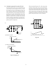
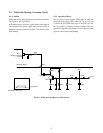
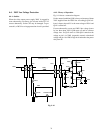
• To restart TV set, repair failure first.
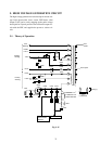
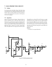
7. X-RAY PROTECTION CIRCUIT
7-1. Outline
In case picture tube using high voltage, when high voltage
rises abnormally due to components failure and circuit mal-
function, there is possible danger that X-RAY leakage in-
creases to affect human body. To prevent it, X-RAY protec-
tion circuit is equipped.
7-2. Operation
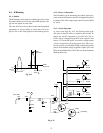
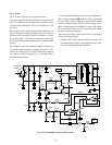
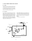
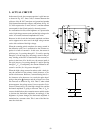
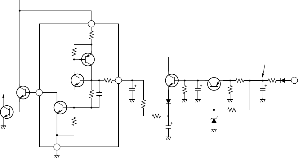
Figure 9-23 shows the circuit diagram. Supposing high volt-
age rises abnormally due to some reason, pulse at pin 9 of
T461 also rises, and detection voltage E
D
rectified by D471
and C471 in X-RAY protection circuit rises. When E
D
rises,
emitter voltage of Q464 divided by R459 and R462 becomes
higher than [zener voltage (6.2V) of D458 + Q464 VBE ].
This causes Q464 turns on to supply base current to Q463.
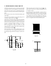
Fig. 9-23 X-RAY protection circuit
R
ELAY
S
R80
Q846
Q845
Tr5
Tr6
Tr7
R11
R12
R9
R10
R19
C1
C894
R879
R467
12V
D459
R468
C458
R458
R462
R459
Q463
Q464
C471
R472
D471
9
T461
D458
14
17
16
Z801
C459
5V
E
D
15


