


80
8. OVER CURRENT PROTECTION CIRCUIT
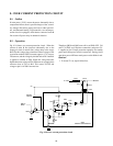
8-1. Outline
If main power (125V) current increases abnormally due to
components failure, there is possible danger of the second-
ary damage like failure getting involved in other part fail-
ure, and abnormal heating. To prevent this, over current pro-
tection circuit is equipped, which detects current of main B
line to turn off power relay in abnormal situation.
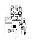
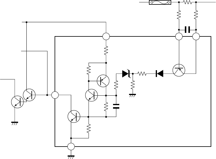
8-2. Operation
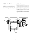
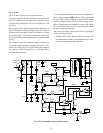
Fig. 9-24 shows over current protection circuit. When the
current of main B line increases abnormally due to the
shortage in load of main B line, voltage drop arises across
R470. By this voltage drop, when base-emitter voltage of Tr8
in protector module (Z801) becomes approx. 0.7V or more,
Tr8 turns on, and the voltage by divided ratio of R15 and R16
is applied to cathode of ZD4. When this voltage becomes
higher than zener voltage of ZD4, ZD4 turns on to supply base
current to base of Tr6 via R14. This causes Tr5 ON and
voltage at pin 16 of Z801 becomes low.
Therefore, QB30 and Q843 turns off to set SR81 OFF. Tr6
and Tr7 in Z801 are in thyristor-connection, and power 5V-
1 supplied at pin 15 keeps protection operation for standby
power until main power switch is turned off. During circuit
operation, power LED near main power switch blinks in red.
Caution:
• To restart TV set, repair failure first.
Fig. 9-24 Over current protection circuit
16
15
17
21
5V
MICON
QA01#7
RELAY
SR80
Q845
Q846
MAIN B
R470
F470
To T461
R479
R471
C472
R16
R15
R14
R12
R11
R9
R10
ZD4
C1
Tr6
Tr5
Tr7
Tr8
D1
Z801
PROTECTOR MODULE