


86
1. OUTLINE
The digital convergence circuit develops outputs to correct
screen distortion and perform color matching. The digital
convergence circuit used is of an all digital type and allows
good adjustments in comprise with a conventional analog type
circuit.
Followings are features of the digital convergence circuit.
1) No adjustment controls (volumes)
2) Registration accuracy increased.
3) Space saved
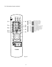
4) Adjustment by a remote control
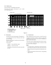
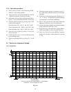
The data adjusted are classed into 4 screens for each screen
mode. These data are stored on E
2
PROMs inside the unit.
The memory size used in this case is 4 Kbits per one screen.
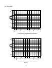
Each screen adjustment is carried out by calling the adjust-
ment screen with the remote control unit supplied and the
adjustment is carried out according to the dimensions speci-
fied for each screen. The control of the unit is carried out in
the I
2
C format.
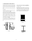
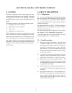
2. CIRCUIT DESCRIPTION
2-1. Configuration
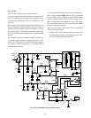
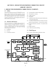
Fig. 11-1 shows a block diagram. The digital convergence
unit consists of Q701 T7K64 which plays a major role, Q707
PLL circuit which locks a sync entered, Q713 E
2
PROM to
store the data, and Q703-5 D/A converter which develops a
correction wave form.
The output signal from the Q703 – 705 D/A converter is
amplified and wave form shaped by Q715, Q717 and Q719,
and comes out from the unit.
The clock signal for the PLL is adjusted by L719 to a refer-
ence frequency of 32 ± 0.1MHz under no input status.
A test pattern generator is also built inside Q701 and devel-
ops R, G, B signals and a Ys switching signal.
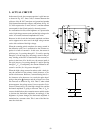
2-2. Circuit Description
(1) With the power turned on, the unit is reset and enters
an operation standby status. And a sync signal of the
unit enters external Q707 and Q701. The signal en-
tered Q707 is counted down by a counter inside the
Q701 and this is used as the reference clock. Q701
works in synchronization with the reference clock sig-
nal and the sync signal.
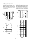
(2) A command is sent from the microcomputer in the unit
and Q701 is set up to load the data in Q713 to the in-
ternal RAM. (8 (horizontal) x 7 (vertical) x 3 (color))
(3) Q701 transfers a serial data specified to Q703 – 705
according to the RAM data. In this case, interpolation
for the RAM data is automatically carried out by a built
-in digital filter inside Q701.
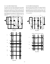
(4) The serial data sent from Q701 are digital-analog con-
verted by Q703 – 705, thus developing the analog type
wave form.
(5) The signals sent from Q703 – 705 are amplified Q715,
Q717, Q719, respectively, and then filtered in the next
stage to smooth and shape the wave form. Thus pro-
cessed signals are used as H and V correction wave
forms for R, G, and B signals.
SECTION XI: DIGITAL CONVERGENCE CIRCUIT