82
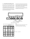
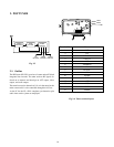
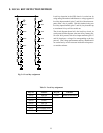
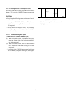
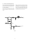
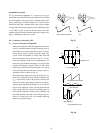
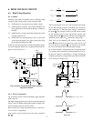
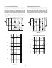
When the negative pulse developed at the point B is inte-
grated with Lm and Csm, its average value appears at Csm
as a negative voltage.
By modulating this voltage with Q460, a waveform of Vm is
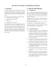
obtained as shown in Fig. 10-3 b). As a result, the voltage
V
S
which is the sum of the power supply voltage V
B
and the
Vm is applied across the S-curve capacitor C
S
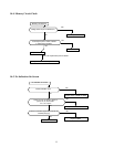
. The V
S
be-
comes as a power source for the deflection yoke as shown in
Fig. 10-4, is applied to the horizontal deflection yoke.
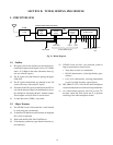
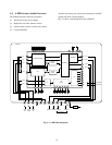
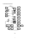
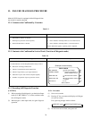
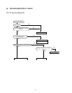
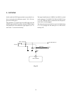
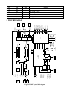
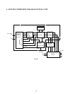
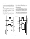
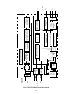
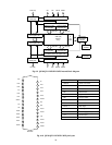
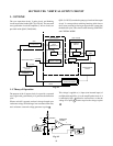
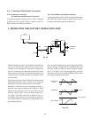
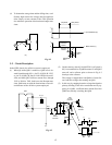
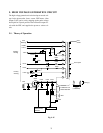
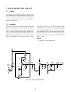
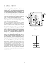
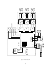
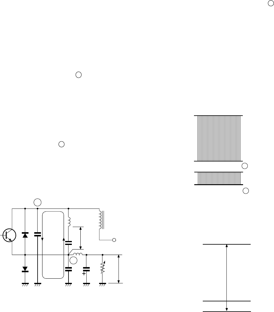
2. DIODE MODULATOR CIRCUIT
In N5SS, the distortion correction is carried out by the ditigal
convergence circuit. So the component of the diode modu-
lator circuit is the same as that of conventional television,
because it is used only for the horizontal oscillation adjust-
ment.
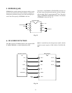
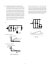
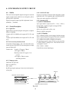
Fig. 10-2 shows a basic circuit of the diode modulator used
in the N5SS.
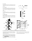
A key point in the modulation circuit shown in Fig. 10-2 is
to develop a negative pulse at point B .
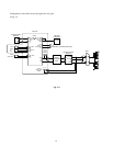
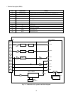
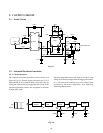
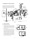
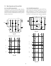
In this circuit, a current loop of the resonant circuit for flyback
period is shown by an arrow, and the energy stored in L
DY
is
transferred to resonant capacitors Cr, Crm in passing through
Cr, Crm, C
S
when the scanning completes. As a result, a
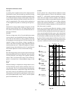
positive, horizontal pulse as shown in Fig.
10-3 a) will appear at Cr, and the current flows into Crm
with the direction as shown. Then a pulse as shown in Fig.
10-3 b) develops at the point B.
On the other hand, since constant amplitude pulses across
Cr, as shown in Fig. 10-3, are applied to the primary wind-
ing, the high voltage of FBT also develops a constant volt-
age.
A
B
H
OUT
DD
Cr
DM
L
DY
FBT
V
B
Cs
Vs
Crm
Csm
Q460
Vm
Lm
Fig. 10-2
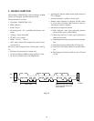
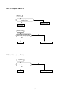
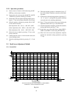
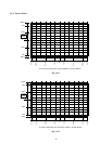
a) Waveform at point A
b) Waveform at point B
0
0
Fig. 10-3
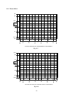
Fig. 10-4
VS
V
B
0