


81
(4) V picture position (neutral voltage setting)
(5) V M-character correction
(6) V EHT correction
(7) H amplitude
(8) L and R pin-cushion distortion correction I (entire area)
– Not used for this model.
(9) L and R pin-cushion distortion correction II (corner
portions at top and bottom) – Not used for this model.
(10) H trapezoid distortion correction – Not used for this
model.
(11) H EHT correction
(12) V AGC time constant switching
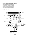
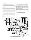
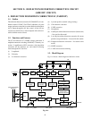
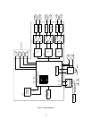
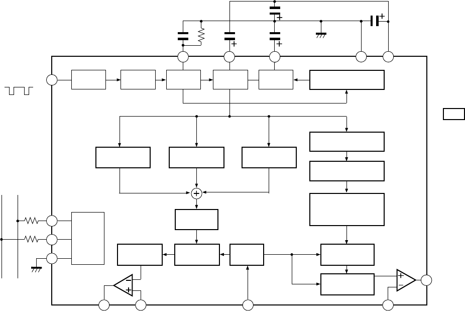
1-3. Block Diagram
Fig. 10-1 shows a block diagram of the basic circuit.
1. DEFLECTION DISTORTION CORRECTION IC (TA8859CP)
1-1. Outline
The deflection distortion correction IC (TA8859CP), in com-
bination with a V/C/D IC (TA1222AN) which has a V pulse
output, performs correction for various deflection distortions
and V output through the I
2
C bus control. All the I
2
C bus
controls are carried out by a microcomputer and can be con-
trolled with the remote control.
1-2. Functions and Features
The IC has functions of V RAMP voltage generation, V
amplitude automatic switching (50/60 Hz), V linearity cor-
rection, V amplification, EHT correction, side pincushion
correction, I
2
C bus interface, etc. and controls following
items through the I
2
C bus lines.
(1) V amplitude
(2) V linearity
(3) V S-character correction
V. Trigger-in
(Bus Control Signal)
SDA SCL
10
9
12
13
14 15
16 5 3
2
4
168
+9V
control through
bus
EW-drive
V drive V. feedback EHT INPUT EW feedback
Waveform
shape
Trigger
det
Puise
Gen.
V. Rame
A G C
V. AGC time
constant SW
H. trapezoid distortion
correction
L-R pincushion
distortion correction I
L-R pincushion
distortion correction II
(Top & bottom comer section)
H.EHT
correction
H. Amplitude
Adj.
H.EHT
input
V. EHT
correction
V. screen
position
V. Amplitude
Adj.
V. M-Character
correction
V. linearity
correction
V. S-character
correction
Logic
Fig. 10-1
SECTION X: DEFLECTION DISTORTION CORRECTION CIRCUIT
(SIDE DPC CIRCUIT)