66
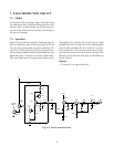
1. OUTLINE
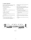
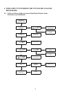
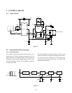
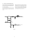
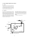
The H deflection circuit works to deflect a beam from left to
right by flowing a sawtooth waveform of 15.625 kHz/15.735
kHz into the DY H deflection coil.
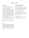
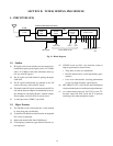
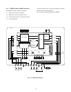
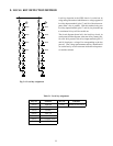
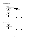
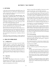
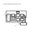
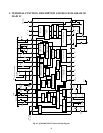
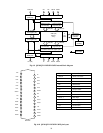
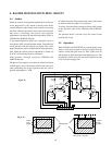
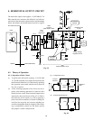
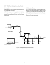
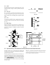
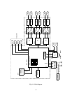
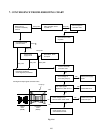
2. HORIZONTAL DRIVE CIRCUIT
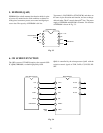
The H drive circuit works to start the H output circuit by
applying H VCC (Q501 DEF power source) to pin 22 of
Q501 (TA1222N) and a bias to the H drive transistor Q402
at the main power on.
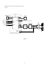
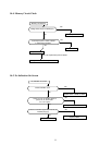
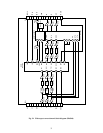
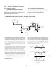
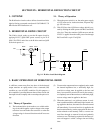
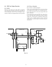
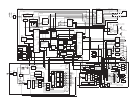
2-1. Theory of Operation
(1) When the power switch is on, the main power supply
of 125V starts to rise. At the same time, AF power sup-
ply 38V also rises.
(2) With 38V line risen, Q430 base voltage which is cre-
ated by dividing the audio power with R433 and D430
also rises. Then, the transistor Q430 turns on and the
H VCC is applied from the audio power line through
R432 and D431 to pin 22 of Q501.
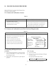
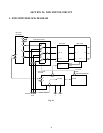
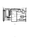
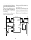
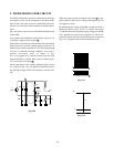
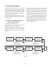
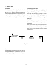
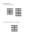
Fig. 9-1 H drive circuit block diagram
81
81 22
R432 Q430 D431
R433
D430
BB80
BB81
L400
SIGNAL
C431 C430
H Vcc
Q501
35V
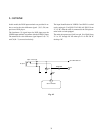
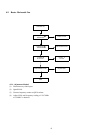
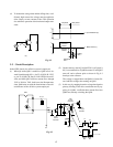
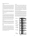
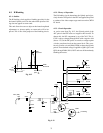
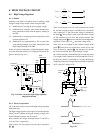
3. BASIC OPERATION OF HORIZONTAL DRIVE
(2) To turn on the output transistor completely and to make
the internal impedance low, a sufficiently high, for-
ward drive voltage must be applied to the base and
heavy base current ib must be flown. On the contrary,
to completely turn off the transistor, a sufficiently high,
reverse voltage must be applied to the base.
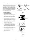
(3) When the transistor is on (collector current is maxi-
mum) condition with the sufficiently high forward volt-
age applied to the base, the transistor can not be turned
off immediately, if a reverse base bias is applied to the
base because minority carriers storaged in the base can
not be reduced to zero instantly. That is, a reverse cur-
rent flows through an external circuit and gradually
reduces to zero. The time lag required for the base cur-
rent to disappear is called a storage time and falling
time.
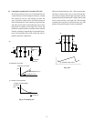
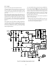
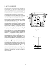
A sufficient current must flow into base of the horizontal
output transistor to rapidly make it into a saturated (ON)
condition or a cut off (OFF) condition. For this purpose, a
drive amplifier is provided between the oscillator circuit and
the output circuit to amplify and to waveshape the pulse volt-
age.
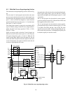
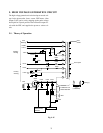
3-1. Theory of Operation
(1) The horizontal drive circuit works as a so called switch-
ing circuit which applies a pulse voltage to the output
transistor base and makes the transistor on when the
voltage swings in forward direction and off in reverse
direction.
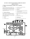
SECTION IX: HORIZONTAL DEFLECTION CIRCUIT