


59
1. OUTLINE
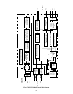
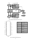
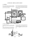
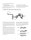
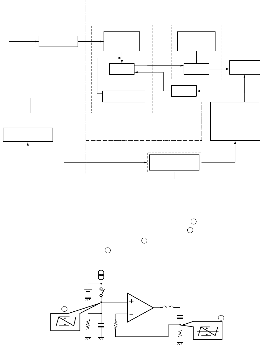
The sync separation circuit, V pulse circuit, and blanking
circuit are provided inside Q501 (TA1222AN). The saw tooth
wave generation circuit and amplifier (V driver circuit) are
provided inside Q302 (TA8859AP).
Q301 (LA7833S) contains the pump up circuit and the output
circuit. V screen position switching function which lowers
the V raster position by flowing an opposite DC current into
the deflection yoke. This circuit is used selecting SUBTITLE
and CINEMA MODE.
MICROPROCESSOR
SYNC SEP.V PULSE/
BLANKING
PULSE DELAY
SAWTOOTH
WAVE
GENERATOR
AMP
Q302 TA8859AP
CONTROL CIRCUIT
Q301 LA7833S
PUMP UP
CIRCUIT
OUTPUT
FEEDBACK
DEFLECTION
YOKE
V-RASTER SHIFT
CIRCUIT
AUTO LIVE
MICROPROCESSOR
( I
2
C BUS)
( I
2
C BUS)
Q501 TA1222AN
V/C/D LSI
WAC
V-BLK
Fig. 8-1
Vp
S: Switch
Differential
amplifier
C2
R3
V2
c
R1 C2 R2
a
V1
L
A
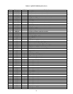
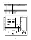
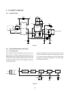
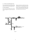
1-1. Theory of Operation
The purpose of the V output circuit is to provide a sawtooth
wave signal with good linearity in V period to the deflection
yoke.
When a switch S is opened, an electric charge charged up to
a reference voltage VP discharges in an constant current rate,
and a reference sawtooth voltage generates at point a .
This voltage is applied to (+) input (non-inverted input) of
an differential amplifier, A. As the amplification factor of A
is sufficiently high, a deflection current flows so that the
voltage V2 at point c becomes equal to the voltage at point
a .
Fig. 8-2
SECTION VIII: VERTICAL OUTPUT CIRCUIT