


27
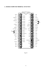
10. ENTERING TO SERVICE MODE
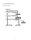
1. PROCEDURE
(1) Press once MUTE key of remote hand unit to indicate
MUTE on screen.
(2) Press again MUTE key of remote hand unit to keep
pressing until the next procedure.
(3) In the status of above (2), wait for disappearing of in-
dication on screen.
(4) In the status of above (3), press MENU (Channel set-
ting) key on TV set.
2. Service mode is not memorized as the last-memory.
3. During service mode, indication S is displayed at upper
right corner on screen.
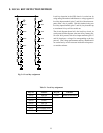
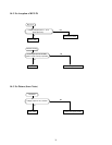
11. TEST SIGNAL SELECTION
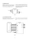
1. In OFF state of test signal, SGA terminal (Pin 20) and
SGV terminal (Pin 21) are kept “L” condition.
2. The function of VIDEO test signal selection is cyclically
changed with VIDEO key (remote unit).
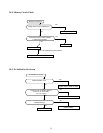
12. SERVICE ADJUSTMENT
1. ADJUSTMENT MENU INDICATION ON/OFF :
MENU key (on TV set)
2. During display of adjustment menu, the followings are
effective.
a) Selection of adjustment item :
POS UP/DN key (on TV/remote unit)
b) Adjustment of each item :
VOL UP/ DN key (on TV / remote unit)
c) Direct selection of adjustment item
R CUTOFF : 1 POS (remote unit)
G CUTOFF : 2 POS (remote unit)
B CUTOFF : 3 POS (remote unit)
d) Data setting for PC unit adjustment
SUB CONTRAST : 4 POS (remote unit)
SUB COLOR : 5 POS (remote unit)
SUB TINT : 6 POS (remote unit)
e) Horizontal line ON/OFF : VIDEO (on TV set)
f) Test signal selection : VIDEO (remote unit)
* In service mode, serviceable items are limited.
3. Test audio signal ON / OFF: 8 POS (remote unit)
* Test audio signal : 1 kHz
4. Self check display : 9 POS (remote unit)
* Cyclic display (including ON/OFF)
5. Initialization of memory :
CALL (remote unit) + POS UP (on TV set)
6. Initialization of self check data :
CALL (remote unit) + POS DN (on TV set)
7. BUS OFF :
CALL (remote unit) + VOL UP (on TV set)
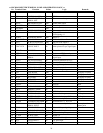
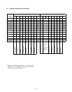
Test Signal No.
0
1
2
3
4
5
6
7
8
9
10
11
12
13
14
15
Name of Pattern
Signal OFF
All black signal + R single color (OSD)
All black signal + G single color (OSD)
All black signal + B single color (OSD)
All black signal
All white signal
W/B
Black cross bar
White cross bar
Black cross hatch
White cross hatch
White cross dot
Black cross dot
H signal (bright area)
H signal (dark area)
Black cross + G signal color
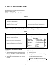
(3) SGA (audio test signal) output should be square wave
of 1 kHz.
Table 3-2