


60
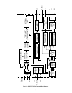
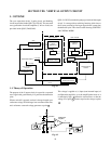
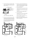
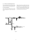
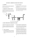
2. V OUTPUT CIRCUIT
2-1. Actual Circuit
31
15
14
13
3
6
8
7
6
4
1
5
2
3
C322
R329
Q501
C321
R320
Q302
+9V
D309
+35V
R301
R330
C319
C314
Q301
C309
C311
R308 C308
D301
C313
R303
L301 R336
R307
L462+L463+L464
R306
R313
C306
R305
C305
R304
C307
D308
Fig. 8-3
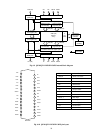
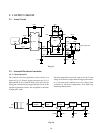
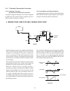
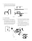
2-2. Sawtooth Waveform Generation
2-2-1. Circuit Operation
The sawtooth waveform generation circuit consists of as
shown in Fig. 8-4. When a trigger pulse enters pin 13, it is
differentiated in the waveform shape circuit and only the
falling part is detected by the trigger detection circuit, to the
waveform generation circuit is not susceptible to variations
of input pulse width.
13
14
15 16
5Vp
DC=0V
WAVEFORM
SHAPE
TRIGGER
DET.
PULSE
GAIN
V. LAMP
AGC
+
+9V
R329
C321 C322 C323
Fig. 8-4
The pulse generation circuit also works to fix the V ramp
voltage at a reference voltage when the trigger pulse enters,
so it can prevent the sawtooth wave start voltage from
variations by horizontal components, thus improving
interlacing characteristics.