


73
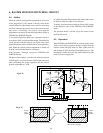
4-3. H Blanking
4-3-1. Outline
The H blanking circuit applies a blanking precisely for the
horizontal flyback period so that undesirable pictures fold-
ing does not appear at screen ends.
This unit allows the users to adjust an horizontal amplitude
adjustment, so, picture quality at screen ends will be im-
proved. This is one of the purposes of the blanking circuit.
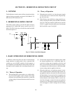
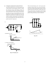
4-3-2. Theory of Operation
The H blanking circuit determines the flyback period pre-
cisely from the AFC pulse in the FBT and applies the period
to emitter of the video output stage transistor on the CRT-D
PC board.
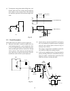
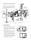
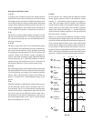
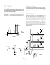
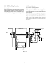
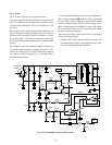
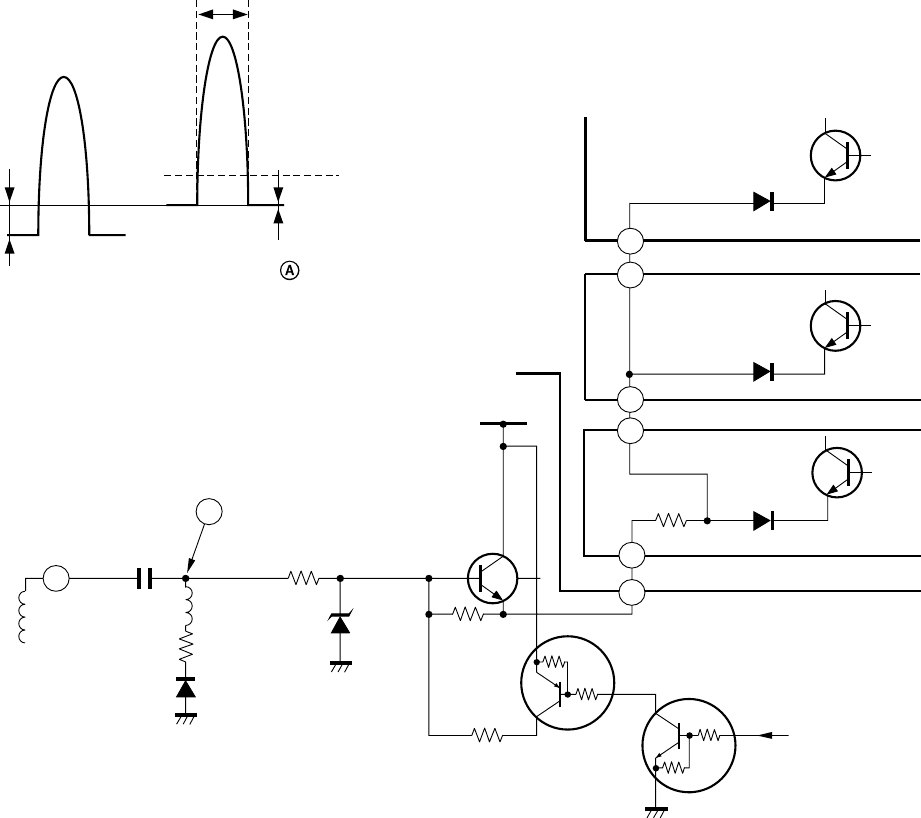
4-3-3. Circuit Operation
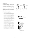
As can be seen from Fig. 9-12, the flyback period of the
AFC pulse in the FBT starts at a negative side from 0V. To
detects this, the DC component is cut with C493. This is,
C493 is always charged through D487 with a negative side
(about –17V) of the AFC pulse. As a result, a voltage at point
A in the waveform rises from the ground level. This wave-
form is sliced in a circuit (R486, D486) to detect the flyback
period. Thus obtained voltage is applied to Q901, Q911, and
Q921 through D904, D914, D927 and cuts off them thereby
blanking the resters.
0V
Approx.
-17V
AFC Pulse
Q487
ON period
D486
Slice level
Waveform at
point
Fig. 9-12
T461 (FBT)
AFC
10
A
Point
C493
D487
R409
R486
D486
R417
R438
V blanking
Q488
Q489
P903
P904
R906
+35V
Q487
D914
D904
Q901
Q911
CRT-D DCB
Deflection/Power PCB
7
6
10
10
D927
Q921
BLUE
CRT/D
GREEN
CRT/D
RED
CRT/D
10
10
L410
Fig. 9-13