


39
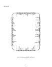
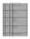
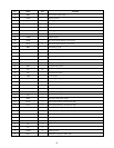
Table 5-1 Names and functions of TC9097F
I/O
I
–
I
–
–
–
–
–
O
–
–
–
O
–
–
–
O
–
–
–
–
–
I
–
–
–
–
I
–
I
I
–
–
I
I
I
–
Name
ISI
VRA2
YSI
NC
VBC
VBD2
VBD4
AVDD
QSO
NC
VBD3
AGND
ISO
VRD1
NC
AVDD
YSO
VBD2
AGND
VBD1
AGND
NC
VFV
VFL1
AVDD
VLM
VDD
HDI
NC
VD1
RESET
NC
NC
TST0
TST1
TST2
NC
No.
1
2
3
4
5
6
7
8
9
10
11
12
13
14
15
16
17
18
19
20
21
22
23
24
25
26
27
28
29
30
31
32
33
34
35
36
37
Function
I color signal input
Reference voltage (low level) for AD1, AD2
Y signal input
–
Bias for clamp 1
Reference voltage for DA2, DA3
Bias 2 (high level) for DA2, DA3
Analog power
Q color signal output
–
Bias 2 (low level) for DA2, DA3
Analog ground
I signal output
Reference voltage for DA1
–
Analog power
Y signal output
Bias 1 (high level) for DA1
Analog ground
Bias 2 (high level) for DA1
Analog ground
–
Connected to VSS or VDD
Connected to VDD
Analog power
1/2 VDD for line memory
Digital power
Composite sync signal input
–
V sync signal input
Reset input (Normally: High level, Reset: Low level)
–
–
Test mode setting (normally connected to VSS)
Test mode setting (normally connected to VSS)
Test mode setting (normally connected to VDD)
–