


29
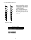
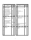
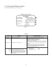
13-4. Understanding Self Diagnosis Indication
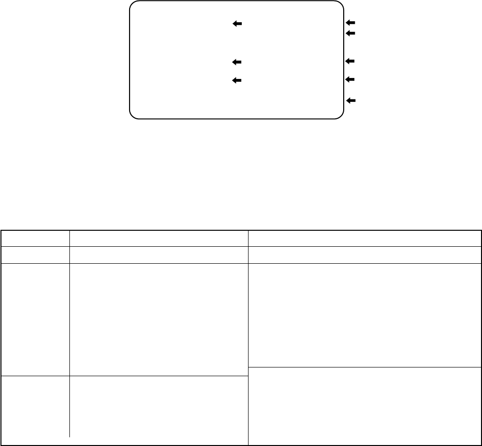
In case that phenomenon always arises. See Fig. 3-7 .
(Example of screen display)
SELF CHECK
Part coce of QA01
Number of operation of
power protection circuit
Short check of bus line
Communication check of
busline
NO. 239XXXX
POWER: 000000
BUS LINE: OK
BUS CONT: OK
BLOCK: UV V1 V2
QV01, QV01S
E
F
B
C
D
Table 3-5
Item
BUS LINE
BUS CONT
BLOCK: UV1
UV2
V1
V2
Contents
Detection of bus line short
Communication state of bus line
The sync signal part in each video signal
supplied from each block is detected.
Then by checking the existence or non of sync
part, the result of self diagnosis is displayed
on screen. Besides, when “9” key on remote
unit is pressed, diagnosis operation is first
executed once.
Instruction of results
Indication of OK for normal result, NG for abnormal
Indication of OK for normal result
Indication of failure place in abnormality
(Failure place to be indicated)
QA02 NG, H001 NG, Q501 NG, H002 NG, QV01 NG, Q302
NG, QY02 NG, HY01 NG, QD04 NG, QM01 NG, Q701 NG
Note:
The indication of failure place is only one place though
failure places are plural. When repair of a failure place
finishes, the next failure place is indicated. (The order of
priority of indication is left side.)
*Indication by color
• Normal block : Green
• Non diagnosis block : Cyan
Fig. 3-7