


68
4. HORIZONTAL OUTPUT CIRCUIT
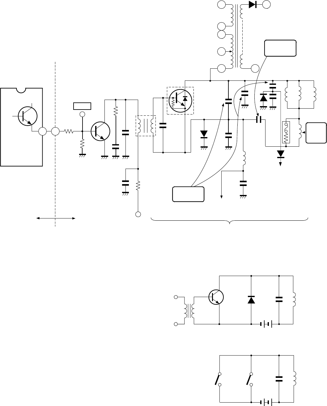
The horizontal output circuit applies a 15.625 kHz/15.734
kHz sawtooth wave current to the deflection coil with mu-
tual action of the horizontal output transistor and the damper
diode, and deflects the electron beam from left to right in
horizontal direction.
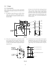
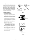
4-1. Theory of Operation
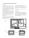
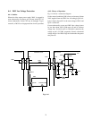
4-1-1. Operation of Basic Circuit
(1) To perform the horizontal scanning, a 15.625 kHz/
15.735 kHz sawtooth wave current must be flown into
the horizontal deflection coil. Theoretically speaking,
this operation can be made with the circuit shown in
Fig. 9-5 (a) and (b).
(2) As the switching operation of the circuit can be re-
placed with switching operation of a transistor and a
diode, the basic circuit of the horizontal output can be
expressed by the circuit shown in Fig. 9-5 (a). That is,
the transistor can be turned on or off by applying a
pulse across the base emitter. A forward switching cur-
rent flows for on-period, and a reverse switching cur-
rent flows through the diode for off-period. This switch-
ing is automatically carried out. The diode used for
this purpose is called a damper diode.
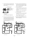
Fig. 9-5
(a) H output basic circuit
(b) H output equivalent circuit
H output
transistor
DCo
L
Deflection
yoke
Resonant
capacitor
Damper
diode
Vcc
Vcc
SW1
SW2
Co
L
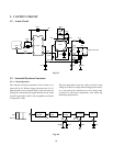
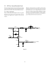
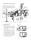
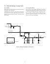
Fig. 9-4
IC501
H. out
Q1
23
83
10
5
2
3
1
HV
8
S-charactor
capacitor
H
linearity
coil
Resonat
capacitor
Diode modulator circuit
To DPC output
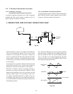
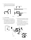
SIGNAL DEF/POWER PCB
TP-33
BB81
R411
R410
C413
C416
R416
125V
Q402
H drive
R415
C417
T401
H drive
transformer
Q404
H output
(With damper diode)
T461
FBT
Deflection yoke
(H coil)
C463
D461
C444
C440
C423
C467
L441
R441
+
C464
+
L461
C343
D444
C418
D443
L462
L463
L464
To High Voltage
Regulator Circuit