


Installation
Rev 3.01 13 Document 900.0315
10/05
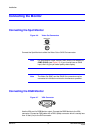
ARI (Alarm Reset In)
An external signal to the Alarm Reset In (ARI) can be used to reset both the Alarm Out
signal and the DVR internal buzzer. Mechanical or electrical switches can be wired to
the ARI (Alarm In) and GND (Ground) connectors. The threshold voltage is below 0.3V
and should be stable at least 0.5 seconds to be detected. Connect the wires to the ARI
(Alarm Reset In) and GND (Ground) connectors.
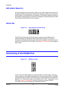
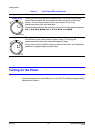
Alarm Out
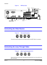
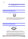
Figure 2-12 Alarm Output Connector Strips
The DVR can activate external devices such as buzzers or lights. Mechanical or
electrical switches can be wired to the NC (Normally Closed) and C (Common)
connectors or NO (Normally Open) and C (Common) connectors. Permitted current is
up to 0.5 A for 125 VAC and 1 A for 30 VDC. See Chapter 3, Configuration for configuring
alarm output.
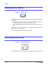
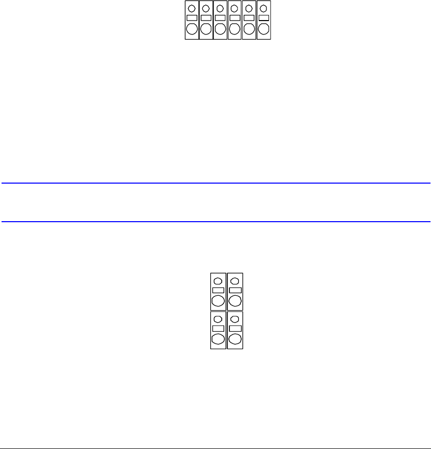
Connecting to the RS485 Port
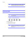
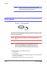
Figure 2-13 RS485 Connector
You an control the DVR remotely by an external device or control system, such as a
control keyboard, using RS485 half-duplex serial communications signals. The RS485
connector can also be used to control PTZ (pan, tilt, zoom) cameras. Connect RX-/TX-
and RX+/TX+ of the control system to the TX-/RX- and TX+/RX+ (respectively) of the
DVR. See Chapter 3, Configuration and the PTZ camera or remote controller
manufacturer's manual for configuring the RS485 connection.
NC C NO NC C NO
RX+ RX-
TX+ TX-