In Case of Problems
28
TLA 700 Series Installation Manual
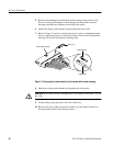
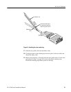
5. Remove the remaining top and bottom probe housings and set them aside.
Do not mix the probe connector-end housings with the podlet connector
housings; the labels are different at each end of the probe.
6. Identify the faulty probe channel at the module end of the cable.
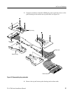
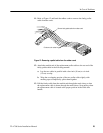
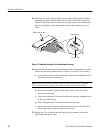
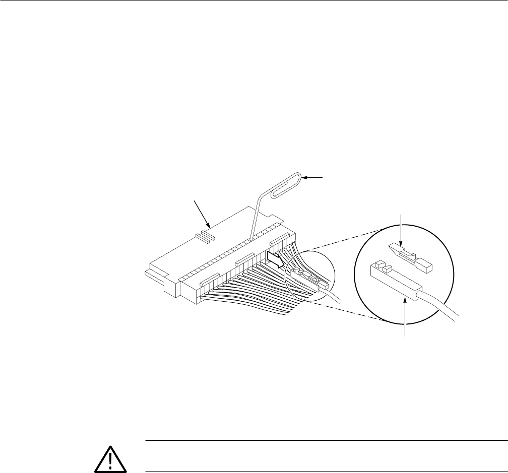
7. Refer to Figure 11 and use a small pointed tool, such as a straightened paper
clip or a mechanical pencil, to release the faulty cable from the cable header
housing. Discard the small plastic retaining snap.
Retaining snap
Cable header housing
Paper clip
Podlet cable
Figure 11: Removing the faulty channel from the probe cable header housing
8. Identify the faulty probe channel at the podlet end of the probe.
CAUTION. Be sure that you have identified the correct podlet cable before you cut
the cable.
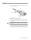
9. Cut the faulty podlet just above the color-coded ring.
10. Remove the color-coded ring and set it aside; you will need to install it on
the replacement cable later in this procedure.


