


Chapter 2 Hardware Installation
23
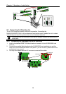
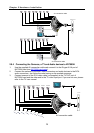
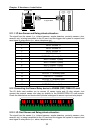
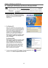
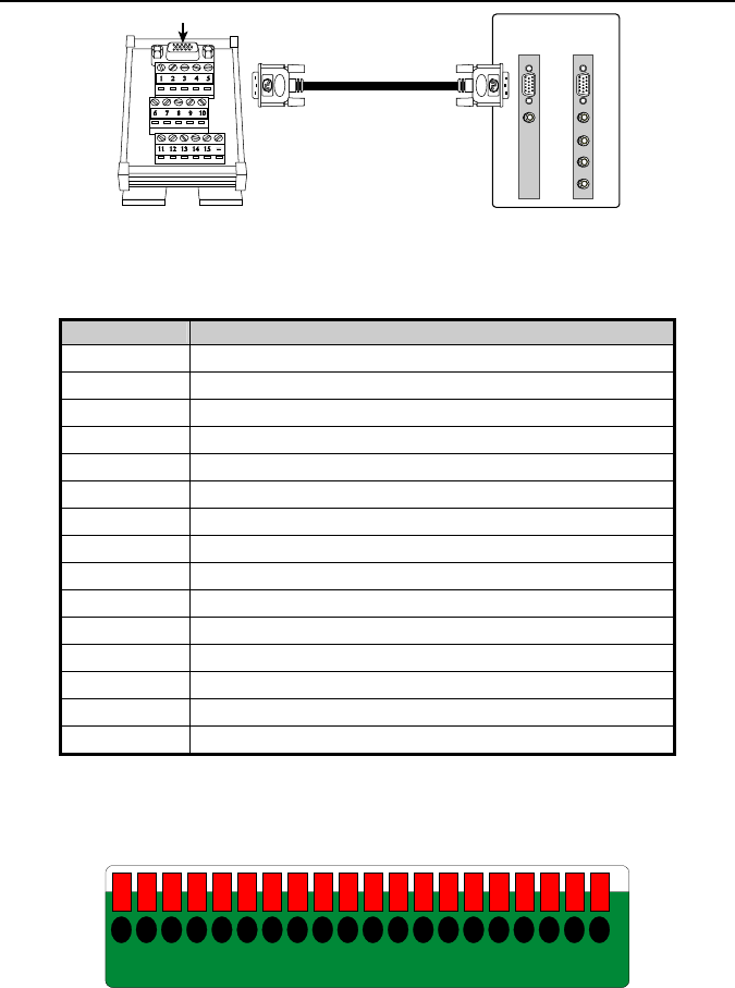
D-Type I/O port
AUDIO IN 1
NV3000
I/O Audio
card
AUDIO IN 1
AUDIO IN 2
AUDIO IN 3
AUDIO IN 4
NV5000
I/O Audio
card
D-type cable
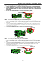
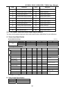
2.11.1 I/O box Sensor and Relay pinhole allocation:
The signal from the sensor (i.e., infrared sensors, smoke detectors, proximity sensors, door
sensors, etc.) is being transmitted to the I/O card, and this triggers the system to respond and
send signal to relay device (i.e., alarm, telephone etc).
Pin # Definition
1 INPUT SIGNAL 1+
2 INPUT SIGNAL 2+
3 INPUT SIGNAL 3+
4 INPUT SIGNAL 4+
5 OUTPUT 3 – Normally Closed
6 INPUT SIGNAL 1-(GND)
7 INPUT SIGNAL 2-(GND)
8 INPUT SIGNAL 3-(GND)
9 INPUT SIGNAL 4-(GND)
10 OUTPUT 3 – Common
11 OUTPUT 1 – Normally Open
12 OUTPUT 1 – Common
13 OUTPUT 2 – Normally Open
14 OUTPUT 2 – Common
15 OUTPUT 3 – Normally Open
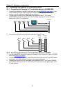
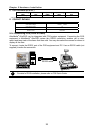
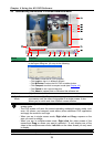
2.12 Connecting the Sensor/Relay device to NV6000 (EXP)/7000H I/O card
The I/O Audio card enables you to connect (4) sensor inputs and (4) relay outputs. Just
connect the external sensor and relay pin directly to the NV6000/7000H I/O card pinhole.
Check the table below and locate which pinhole is assigned to sensor input and relay output.
2019181716151413121110987654321
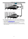
2.12.1 I/O Card Sensor and Relay pinhole allocation:
The signal from the sensor (i.e., infrared sensors, smoke detectors, proximity sensors, door
sensors, etc.) is being transmitted to the I/O card and this triggers the system to respond and
send signal to relay device (i.e., alarm, telephone etc).