


Outputs
108
VM200 UserÕs Guide
Overview
The VM200 features several types of outputs, including the stereo
buss output, the recording buss output, the ADAT and S/P DIF dig-
ital outputs, and auxiliary (AUX) and effect (EFF) sends.
You can control much of the signal routing by setting parameters on
the
ROUTING
function page. You can display the
ROUTING
function page
by pressing the [ROUTING/PHASE] key.
The Effect Send capabilities of the VM200 are explained in more
detail in the “Effects” chapter page 123.
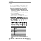
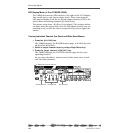
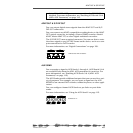
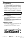
ST BUSS OUT
The VM200 converts the digital stereo buss (ST BUSS) signal to an
analog signal using 20-bit 128-times oversampling D/A converters.
It then outputs it from the ST BUSS OUT unbalanced phone jack
(located on the rear panel) with a –10 dB nominal output level.
To output signals from these connectors, you need to route channel
signals to ST BUSS using the
ROUTING
function page, which you can
access by pressing the
[ROUTING/PHASE]
key. (See “Input Channels”
on page 59.)
For more information, see “Using the ST BUSS OUT” on page 110.
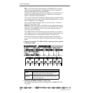
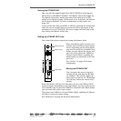
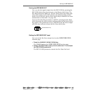
REC BUSS OUT
The VM200 converts the digital stereo signal output from the REC
BUSS to an analog signal using 20-bit 128-times oversampling D/A
converters. The analog signal is then output from the rear panel via
the REC BUSS OUT unbalanced phone jacks with a –10 dB nominal
output level.
To output signals from these connectors, you need to route channel
signals to REC BUSS using the
ROUTING
function page accessed via
the [ROUTING/PHASE] key. (See “Input Channels” on page 59.)
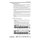
The signals from the REC BUSS are also routed to input channels
1–8. More specifically, the left channel signals are routed to channels
1, 3, 5, and 7, and the right channel signals are routed to channels
2, 4, 6, and 8. You can then route the signals directly to the ADAT
OUTS 1–8. In this way, you can output two mixes simultaneously.
For more information, see “Using the REC BUSS OUT” on page 112.
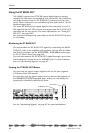
RL
ST BUSS OUT
ST BUSS OUT
R4 L3
ADD.AUX SEND
REC BUSS OUT
REC BUSS OUT