Phantom Power for Input Channels 1–4
VM200 User’s Guide
61
Phantom Power for Input Channels 1–4
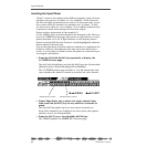
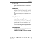
The VM200 supplies optional phantom power (+48 V) to the XLR con-
nectors. You can turn the phantom power on or off using the switches
on the rear panel as shown in the figure above.
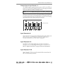
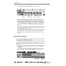
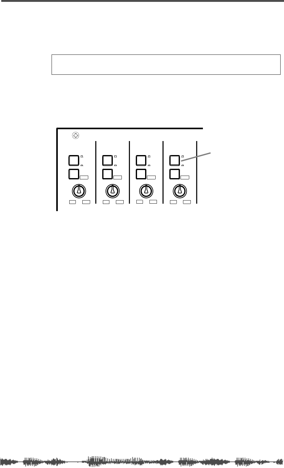
Specify the connector you wish to use by pressing (or not pressing) the
A/B input selectors on the top panel (shown in the figure below). The
A setting (unpressed) selects the XLR input connector; the B setting
(depressed) selects the phone jack input connector.
Input Channels 5–8
Input channels 5–8 accept only unbalanced phone jacks. (These con-
nectors do not accept XLR inputs or balanced analog inputs.)
For more information, see “Rear Panel” on page 38.
Input Channels 9–16
In addition to the analog signals you can input to channels 1
through 8, you can assign digital ADAT inputs to channels 9-16.
Refer to “Digital Connections” on page 159 for more information.
Input Channels 17–20
Input channels 17–20 are used for internal effect returns from the
EFF1 or EFF2 effects processor.
Caution:
Turn on the phantom power only after you connect a balanced XLR
component (such as a condenser microphone) to the XLR input connector.
INPUT 4INPUT 3INPUT 2INPUT 1
PAD
26dB
A
B
PAD
26dB
A
B
PAD
26dB
A
B
PAD
26dB
A
B
-16
-60
+10
-34
-16
-60
+10
-34
-16
-60
-16 -60
TRIMTRIMTRIMTRIM
+10
-34
+10
-34
A/B Input selector


