Input Channels
70 VM200 User’s Guide
THE [PAIR/GROUP] key and all [EQ EDIT], [SOLO], and [ON] keys
start to flash.
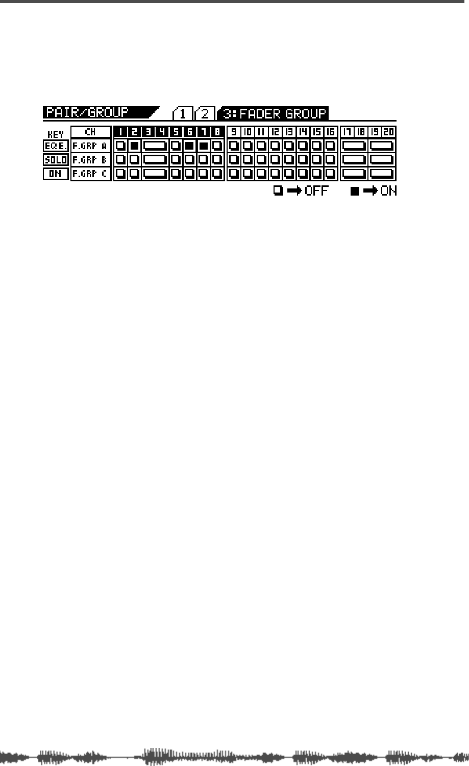
In the following example, channels 2, 6, and 7 are assigned to
Fader Group A. (No other channels are assigned to Fader
Groups.)
2. Press the [EQ EDIT] keys for the faders you wish to add to
Fader Group A.
The
[EQ EDIT] keys light up and the corresponding indicators on the
display turn on (highlight).
3. Press the [SOLO] keys for the faders you wish to add to Fader
Group B.
The
[SOLO] keys light up and the corresponding indicators on the
display turn on (highlight).
4. Press the [ON] keys for the faders you wish to add to Fader
Group C.
The
[ON] keys light up and the corresponding indicators on the dis-
play turn on (highlight).
5. To remove a fader from the fader group, press the correspond-
ing
[EQ EDIT], [SOLO], or [ON] key.
The key resumes flashing and the corresponding display indicator
turns off.
6. Press the [EXIT] key or the [CHANNEL/METER] key to return to
Channel Edit mode.
Viewing Input Channel Settings
The CHANNEL VIEW function page enables you to view the settings for
any input channel.
You cannot adjust any parameters on the CHANNEL VIEW function page.
(If you try to adjust the pan setting, the VM200 displays the CHANNEL
EDIT function page.)
1. Press the [CH VIEW] key to display the 1:CH VIEW function page.
The
[CH VIEW] key and the [EQ EDIT] keys for all viewable channels
flash. The selected Page Select key lights up; unselected Page Select
keys flash.
