Input Channels
66
VM200 User’s Guide
The VM200 displays the
CHANNEL EDIT
function page.
2.
Use the Page Select keys to select the target channel layer.
3.
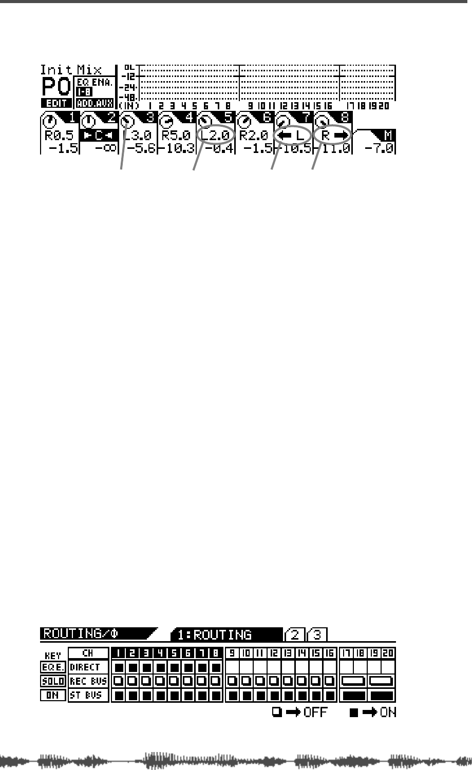
Use the panpot rotary controls to make the pan settings.
The display shows a dial icon for each channel that visually indi-
cates the pan position. The display also includes numerical val-
ues—such as L2.0 or R3.7—that provide precise pan position
data.
If you pan hard right or hard left (that is, fully right or left), the
numerical value changes to a left or right arrow to indicate that
the maximum has been reached.
The pan settings range from L10.0 to R10.0 in increments of 0.5
(although you’ll never see R10.0 or L10.0 indications, because
these settings are the maximum value and are replaced by the
arrow).
Routing Input Channels
You can control input channel routing by using the on/off software
switches on the
ROUTING
function page.
The
ROUTING
function page includes switches that can route channels
1–20 to the Rec Buss and Stereo Buss, and channels 1–8 to the
ADAT Direct outputs. (You cannot route channels 9–20 to the ADAT
Direct outs.)
1.
Press the
[ROUTING/PHASE]
key to display the
1:ROUTING
func-
tion page.
The [EQ EDIT], [SOLO], and [ON] keys start to flash (indicating
their availability). The [ROUTING/PHASE] key also flashes.
hard left hard rightpanpot icon numeric pan value


