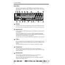
Rear Panel
VM200 UserÕs Guide
39
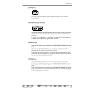
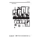
AUX SEND
AUX SEND 1 and 2 are a pair of unbalanced 1/4-inch phone jacks
that can output an auxiliary signal to drive external effects, for
example.
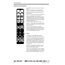
Inputs 1 - 4: XLR or Phone Connectors (A or B)
Input channels 1 - 4 accept either balanced XLR inputs (XLR-3-32
type), or balanced/unbalanced (1/4-inch) phone plugs. (Input 1-4
Phones connectors accept either balanced or unbalanced analog
input.)
If you are inserting a phone plug, press the A/B switch for channels
1 through 4 to select the B inputs.
If you are inserting an XLR-type plug, leave the A/B switch
“unpressed” to select the A inputs. You can switch phantom power to
the XLR connectors on or off using switches located beneath each
connector. (Many condenser microphones, for example, require phan-
tom power.)
These inputs have a nominal input range of -60 dB to +10 dB.
+48 Phantom Power
Turn on this switch for XLR microphones or devices connected to
XLR inputs that require phantom power.
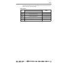
Inputs 5 - 8: Phone Connectors
Input channels 5 through 8 accept unbalanced phone plugs.
These inputs are designed for use with line-level sources (e.g., a syn-
thesizer keyboards, effects processors, or other devices).
These inputs have a nominal input range of -60 dB to +10 dB.
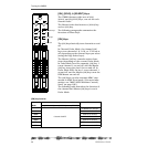
Inserts 1-4: Phone Connectors
The Insert connectors are stereo-type phone jacks.
You can connect an external effects unit to these connectors using an
insert cable to send the signal to the effects unit and return it to the
VM200. (For more information, see “Insert Channels 1–4” on page 62.)
The Insert connectors allow you to insert a signal into the signal chain
after the PAD switches and TRIM knobs.
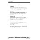
AC In
Insert the female end of the AC power cable into this connector. Con-
nect the male end to an AC electrical outlet of the appropriate voltage
for your area.


