


Chapter 7 Application Programming • 146 USER MANUAL
The corresponding velocity for the motor is assigned to the VEL variable.
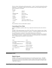
Instruction
#A
JG0
BGX
#B
VIN=@AN[1]
VEL=VIN*20000
JG VEL
JP #B
EN
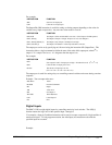
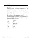
Position Control by Joystick
This system requires the position of the motor to be proportional to the joystick angle. Furthermore,
the ratio between the two positions must be programmable. For example, if the control ratio is 5:1, it
implies that when the joystick voltage is 5 Volts, corresponding to 1028 counts, the required motor
position must be 5120 counts. The variable V3 changes the position ratio.
INSTRUCTION FUNCTION
#A Label
V3=5 Initial position ratio
DP0 Define the starting position
JG0 Set motor in jog mode as zero
BGX Start
#B
V1=@AN[1] Read analog input
V2=V1*V3 Compute the desired position
V4=V2-_TPX-_TEX Find the following error
V5=V4*20 Compute a proportional speed
JG V5 Change the speed
JP #B Repeat the process
EN End
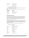
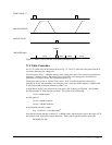
Backlash Compensation by Sampled Dual-Loop
The continuous dual loop, enabled by the DV1 function is an effective way to compensate for
backlash. In some cases, however, when the backlash magnitude is large, it may be difficult to
stabilize the system. In those cases, it may be easier to use the sampled dual loop method described
below.
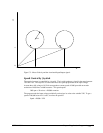
This design example addresses the basic problems of backlash in motion control systems. The
objective is to control the position of a linear slide precisely. The slide is to be controlled by a rotary
motor, which is coupled to the slide by a leadscrew. Such a leadscrew has a backlash of 4 micron, and
the required position accuracy is for 0.5 micron.
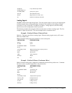
The basic dilemma is where to mount the sensor. If you use a rotary sensor, you get a 4 micron
backlash error. On the other hand, if you use a linear encoder, the backlash in the feedback loop will
cause oscillations due to instability.