


USER MANUAL Chapter 3 Connecting Hardware • 37
Chapter 3 Connecting Hardware
Overview
The DMC-13X8 provides optoisolated digital inputs for forward limit, reverse limit, home, and
abort signals. The controller also has 8 optoisolated, uncommitted inputs (for general use) as well
as 8 TTL outputs and 8 analog inputs configured for voltages between +/- 10 volts.
The DMC-13X8 also have an additional 64 configurable TTL I/O which can be connected to the IOM-
1964 optoisolation module or to OPTO-22 I/O racks. Configuration information for the extended I/O
may be found in the appendix.
This chapter describes the inputs and outputs and their proper connection.
If you plan to use the auxiliary encoder feature of the DMC-13X8, you must also order and connect the
36 pin high-density cable. This cable connects from the auxiliary encoder connector on the DMC-
13X8 to either the ICM-1900 via the CB-36-25 or to the ICM-2908.
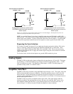
Using Optoisolated Inputs
Limit Switch Input
The forward limit switch (FLSx) inhibits motion in the forward direction immediately upon activation
of the switch. The reverse limit switch (RLSx) inhibits motion in the reverse direction immediately
upon activation of the switch. If a limit switch is activated during motion, the controller will make a
decelerated stop using the deceleration rate previously set with the DC command. The motor will
remain on (in a servo state) after the limit switch has been activated and will hold motor position.
When a forward or reverse limit switch is activated, the current application program that is running
will be interrupted and the controller will automatically jump to the #LIMSWI subroutine if one exists.
This is a subroutine which the user can include in any motion control program and is useful for
executing specific instructions upon activation of a limit switch. Automatic Subroutines are discussed
in Chapter 6.
After a limit switch has been activated, further motion in the direction of the limit switch will not be
possible until the logic state of the switch returns back to an inactive state. This usually involves
physically opening the tripped switch. Any attempt at further motion before the logic state has been
reset will result in the following error: “022 - Begin not possible due to limit switch” error.
The operands, _LFx and _LRx, contain the state of the forward and reverse limit switches, respectively
(x represents the axis, X,Y,Z,W etc.). The value of the operand is either a ‘0’ or ‘1’ corresponding to
the logic state of the limit switch. Using a terminal program, the state of a limit switch can be printed
to the screen with the command, MG _LFx or MG _LFx. This prints the value of the limit switch
operands for the 'x' axis. The logic state of the limit switches can also be interrogated with the TS
command. For more details on TS see the Command Reference.