


Chapter 4 Communication • 46 USER MANUAL
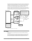
data to the DMC-13X8. The CONTROL register may be read or written to and is used for controlling
communication, flags and interrupts.
Simplified Communication Procedure
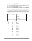
The simplest approach for communicating with the DMC-13X8 is to check bits 4 and 5 of the
CONTROL register at address N+3. Bit 4 is for WRITE STATUS and bit 5 is for READ STATUS.
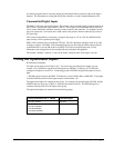
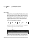
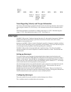
Status Bit Name Logic State Meaning
5 READ 0 Data to be read
5 READ 1 No data to be read
4 WRITE 0 Buffer not full, OK to write up to 16 characters
4 WRITE 1 Buffer almost full. Do not send data
Read Procedure
To receive data from the DMC-13X8, read the CONTROL register at address N+3 and check bit 5. If
bit 5 is zero, the DMC-13X8 has data to be read in the READ register at address N+1. Bit 5 must be
checked for every character read and should be read until it signifies empty. Reading data from the
READ register when the register is empty will result in reading an FF hex.
Write Procedure
To send data to the DMC-13X8, read the CONTROL register at address N+3 and check bit 4. If bit 4
is zero, the DMC-13X8 FIFO buffer is not almost full and up to 16 characters may be written to the
WRITE register at address N+1. If bit 4 is one, the buffer is almost full and no additional data should
be sent. The size of the buffer may be changed (See the following section “Changing Almost Full
Flags”).
Any high-level computer language such as C, Basic, Pascal or Assembly may be used to communicate
with the DMC-13X8 as long as the READ/WRITE procedure is followed as described above. The
specific communications interface used will be determined by the customer and the host VME in the
system.
Advanced Communication Techniques
Changing Almost Full Flags
The Almost Full flag (Bit 4 of the control register) can be configured to change states at a different
level from the default level of 16 characters.
The level, m, can be changed from 16 up to 256 in multiples of 16 as follows:
1. Write a 5 to the CONTROL register at address N+3.
2. Write the number m-16 to the CONTROL register where m is the desired Almost Full level
between 16 and 256.
For example, to extend the Almost Full level to 256 bytes, write a 5 to address N+3. Then write a 240
to address N+3.
Clearing FIFO Buffer
The FIFO buffer may be cleared by writing the following sequence:
Read N+3 address