


USER MANUAL Chapter 10 Theory of Operation • 161
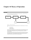
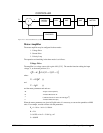
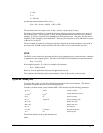
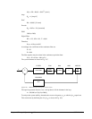
DIGITAL
FILTER
Σ
ZOH DAC
ENCODER
AMP MOTOR
CONTROLLER
R
C
X
Y
VE
P
Figure 10.4 - Functional Elements of a Motion Control System
Motor-Amplifier
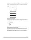
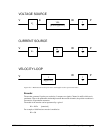
The motor amplifier may be configured in three modes:
1. Voltage Drive
2. Current Drive
3. Velocity Loop
The operation and modeling in the three modes is as follows:
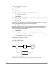
Voltage Drive
The amplifier is a voltage source with a gain of Kv [V/V]. The transfer function relating the input
voltage, V, to the motor position, P, is
(
)
(
)
[]
PV K KSST ST
Vt m e
=++11
where
TRJK
m
t
=
2
[s]
and
T
L
R
e
=
[s]
and the motor parameters and units are
K
t
Torque constant [Nm/A]
R
Armature Resistance Ω
J
Combined inertia of motor and load [kg.m
2
]
L Armature Inductance [H]
When the motor parameters are given in English units, it is necessary to convert the quantities to MKS
units. For example, consider a motor with the parameters:
K
t
= 14.16 oz - in/A = 0.1 Nm/A
R = 2 Ω
J = 0.0283 oz-in-s
2
= 2.10
-4
kg . m
2
L = 0.004H