


USER MANUAL Chapter 2 Getting Started • 29
Step 7C. Connect Step Motors
In Stepper Motor operation, the pulse output signal has a 50% duty cycle. Step motors operate open
loop and do not require encoder feedback. When a stepper is used, the auxiliary encoder for the
corresponding axis is unavailable for an external connection. If an encoder is used for position
feedback, connect the encoder to the main encoder input corresponding to that axis. The commanded
position of the stepper can be interrogated with RP or DE. The encoder position can be interrogated
with TP.
The frequency of the step motor pulses can be smoothed with the filter parameter, KS. The KS
parameter has a range between 0.5 and 8, where 8 implies the largest amount of smoothing. See
Command Reference regarding KS.
The DMC-13X8 profiler commands the step motor amplifier. All DMC-13X8 motion commands
apply such as PR, PA, VP, CR and JG. The acceleration, deceleration, slew speed and smoothing are
also used. Since step motors run open-loop, the PID filter does not function and the position error is
not generated.
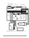
To connect step motors with the DMC-13X8 you must follow this procedure:
Step A. Install SM jumpers
Each axis of the DMC-13X8 that will operate a stepper motor must have the
corresponding stepper motor jumper installed. For a discussion of SM jumpers, see
section “Step 2. Install Jumpers on the DMC-13X8”.
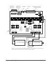
Step B. Connect step and direction signals
For each axis of stepper control, connect the step and direction signals from the controller
to respective signals on your step motor amplifier. (These signals are labeled PULSX
and DIRX for the X-axis on the ICM-1900). Consult the documentation for your step
motor amplifier.
Step C. Configure DMC-13X8 for motor type using MT command. You can configure the
DMC-13X8 for active high or active low pulses. Use the command MT 2 for active high
step motor pulses and MT -2 for active low step motor pulses. See description of the MT
command in the Command Reference.
Step 8. Tune the Servo System
The final step for setting up the motion control system is adjusting the tuning parameters for optimal
performance of the servo motors (standard or sinusoidal commutation). The system compensation
provides fast and accurate response and the following presentation suggests a simple and easy way for
compensation.
The filter has three parameters: the damping, KD; the proportional gain, KP; and the integrator, KI.
The parameters should be selected in this order.
To start, set the integrator to zero with the instruction
KI 0 (CR) Integrator gain
and set the proportional gain to a low value, such as
KP 1 (CR) Proportional gain
KD 100 (CR) Derivative gain
For more damping, you can increase KD (maximum is 4095). Increase gradually and stop after the
motor vibrates. A vibration is noticed by audible sound or by interrogation. If you send the command