


Chapter 2 Getting Started • 16 USER MANUAL
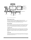
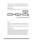
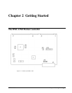
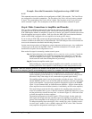
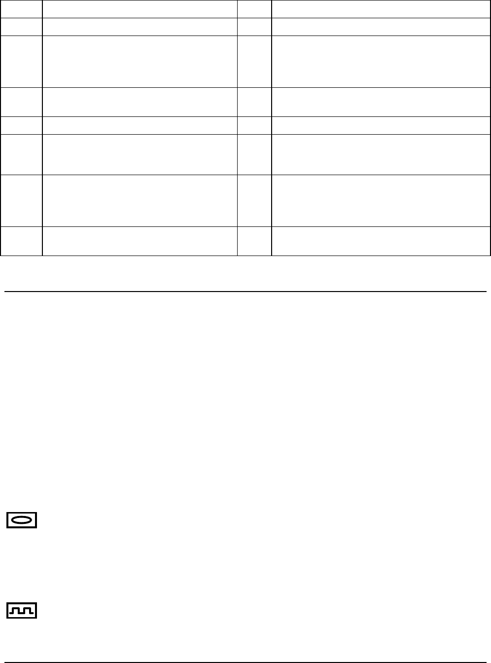
1 Flash EEPROM J6 VME Connector
2 RAM JP1 Master Reset & UPGRD jumpers
3 Motorola 68331 microprocessor JP3 INCOM & LSCOM jumpers. Used for
bypassing opto-isolation for the limit, home, and
abort switches and the digital inputs IN1 - IN8.
See section “Bypassing Opto-Isolation”, Chap3.
4 GL-1800 custom gate array JP5 Jumpers used for configuring stepper motor
operation on axes 1-4.
5 Error LED JP9 IRQ jumper. Interrupts may be set on IRQ 1–7.
J1 100-pin high density connector for axes 1-4.
(Part number Amp #2-178238-9)
JP10 Address jumpers. The base address of the
controller is FFF0. Address jumpers A4-A15
may be set as offsets to that address
J3 80 Pin high-density connector for 64
extended I/O points.
JP11 IAD1-IAD4 allows transfer of the IRQ between
the controller and host. This three bit binary
combination must be set equal to the IRQ line
chosen.
J5 26-pin header connector for the auxiliary
encoder cable. (Axes 1-4)
Note: Above schematics are for most current controller revision. For older revision boards, please refer to Appendix.
Elements You Need
Before you start, you must get all the necessary system elements. These include:
1. DMC-13X8, (1) 100-pin cable and (1) ICM-1900. Connection to the extended I/O can be
made through the IOM-1964 opto-isolation module. Using the IOM-1964 requires (1)
IOM-1964, (1) CB-50-100 and (1) 100 pin cable.
2. Servo motors with Optical Encoder (one per axis) or step motors.
3. Power Amplifiers.
4. Power Supply for Amplifiers.
5. VME host and user interface.
The motors may be servo (brush type or brushless) or steppers. The amplifiers should be suitable for
the motor and may be linear or pulse-width-modulated. An amplifier may have current feedback,
voltage feedback or velocity feedback.
For servo motors in current mode, the amplifiers should accept an analog signal in the +/-10 Volt range
as a command. The amplifier gain should be set such that a +10V command will generate the
maximum required current. For example, if the motor peak current is 10A, the amplifier gain should
be 1 A/V. For velocity mode amplifiers, a command signal of 10 Volts should run the motor at the
maximum required speed. Set the velocity gain so that an input signal of 10V, runs the motor at the
maximum required speed.
For step motors, the amplifiers should accept step and direction signals. For start-up of a step motor
system refer to Step 7c “Connecting Step Motors”.