


Appendices • 186 USER MANUAL
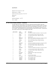
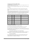
The command, OP, may also be used to set output bits, specified as blocks of data. The OP command
accepts 5 parameters. The first parameter sets the values of the main output port of the controller
(Outputs 1-8, block 0). The additional parameters set the value of the extended I/O as outlined:
OP m,a,b,c,d
where m is the decimal representation of the bits 1-8 (values from 0 to 255) and a,b,c,d represent the
extended I/O in consecutive groups of 16 bits. (values from 0 to 65535). Arguments which are given
for I/O points which are configured as inputs will be ignored. The following table describes the
arguments used to set the state of outputs.
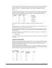
Argument Blocks Bits Description
m 0 1-8 General Outputs
a 2,3 17-32 Extended I/O
b 4,5 33-48 Extended I/O
c 6,7 49-64 Extended I/O
d 8,9 65-80 Extended I/O
For example, if block 8 is configured as an output, the following command may be issued:
OP 7,,,,7
This command will set bits 1,2,3 (block 0) and bits 65,66,67 (block 8) to 1. Bits 4 through 8 and bits
68 through 80 will be set to 0. All other bits are unaffected.
When accessing I/O blocks configured as inputs, use the TIn command. The argument 'n' refers to the
block to be read (n=0,2,3,4,5,6,7,8 or 9). The value returned will be a decimal representation of the
corresponding bits.
Individual bits can be queried using the @IN[n] function (where n=1 through 8 or 17 through 80). If
the following command is issued;
MG @IN[17]
the controller will return the state of the least significant bit of block 2 (assuming block 2 is configured
as an input).
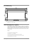
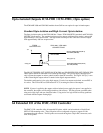
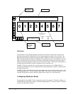
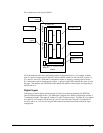
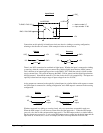
Connector Description:
The DMC-13X8 controller has a single 80-pin high density connector for the extended I/O. This cable
may then be connected to either the IOM-1964 directly, or to two 50 Pin IDC header connectors on the
CB-50-80. The 50-pin IDC connectors are compatible with I/O mounting racks such as Grayhill
70GRCM32-HL and OPTO-22 G4PB24.
Note for interfacing to OPTO-22 G4PB24: When using the OPTO-22 G4PB24 I/O mounting rack,
the user will only have access to 48 of the 64 I/O points available on the controller. Block 5 and Block
9 must be configured as inputs and will be grounded by the I/O rack.
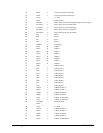
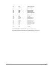
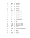
J6 50-PIN IDC
PIN SIGNAL BLOCK BIT @IN[n],
@OUT[n]
BIT #
1. I/O 4 40 7
3. I/O 4 39 6
5 I/O 4 38 5
7. I/O 4 37 4
9. I/O 4 36 3
11. I/O 4 35 2